 |
|||
|
|
|||
|
|
|||
| ||||||||||
|
|
 TM 11-6625-2884-30/NAVAIR 16-35TS3615-2
INTRODUCTION(Continued)
Section I provides the overall block diagram description. The following units
of the bench test set will be discussed:
CONTROL PANEL ASSEMBLY 1A1
STATUS PANEL ASSEMBLY 1A2
RF MODULATION ASSEMBLY 1A3
RF MODULATION ASSEMBLY 1A4
Section II provides a more detailed description of each of the major functions
of the bench test set.
Foldout block diagrams and functional block diagrams of the BTS are included in
the rear of this manual in Appendix C for reference purposes.
BLOCK DIAGRAM
2-2.
(Refer to figure F0-1.) The bench test set consists of four assemblies,
Control Panel Assembly 1A1, Status Panel Assembly 1A2, and two identical RF
Modulation Assemblies 1A3 and 1A4.
a. Control Panel Assembly 1A1. (Refer to figure FO-1.)
The control panel assembly is divided into two functional areas.
Power, Control, Error and Status to and from LRU-1.
Power to the bench test set for AC Power, distribution, cooling, and
YIG FILTER CONTROL.
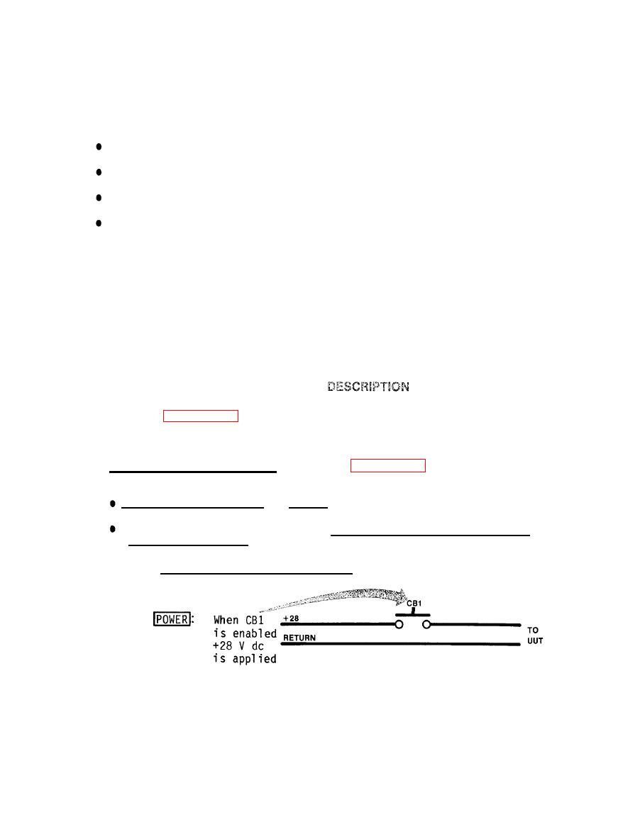
(1) Power, Control, Error & Status
to UUT
|
|
Privacy Statement - Press Release - Copyright Information. - Contact Us |
