 |
|||
|
|
|||
|
Page Title:
BLOCK DIAGRAM |
|
||
| ||||||||||
|
|
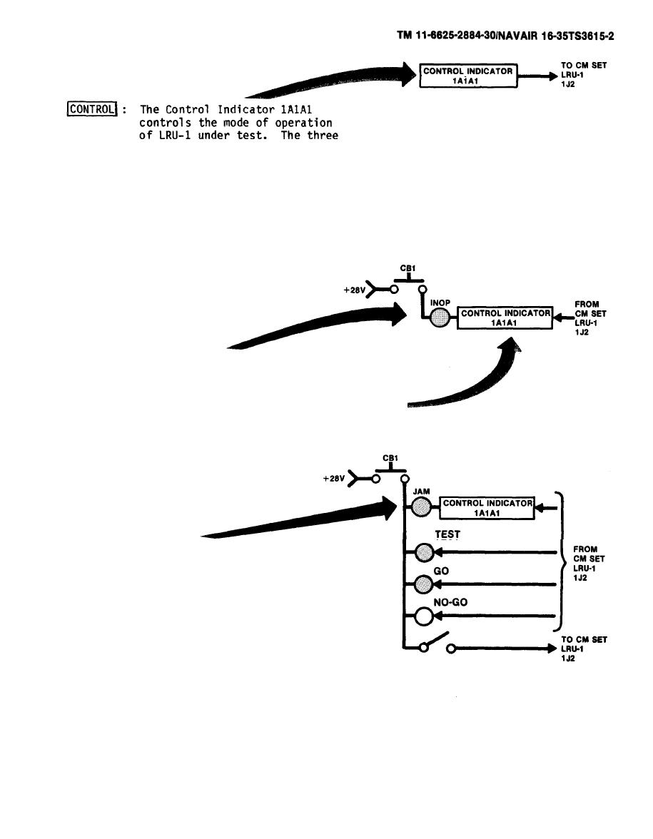
 modes of operation are:
OFF -
No power applied to LRU-1
STBY - +28 V applied to enable
receiver circuits
OPR - Enables some transmitting
circuits
The INOP indicator lights when a
fault signal is received from LRU-1
under test. The signal from LRU-1
enables a relay in Control Indicator
(1A1A1) . A ground return from the
relay completes the circuit via CB1
to +28 V,
The JAM indicator lights when LRU-1
is transmitting active ECM. The
signal from LRU-1 enables a relay in
Control Indicator (1A1A1). A ground
return from the relay completes the
circuit via CB1 to +28 V.
The TEST indicator lights when
LRU-1 self-test (BITE) is
selected.
The GO [or the NO-GO) indicator
lights to indicate that LRU-1 is
(or is not) functioning correctly.
2-3
|
|
Privacy Statement - Press Release - Copyright Information. - Contact Us |