 |
|||
|
|
|||
|
Page Title:
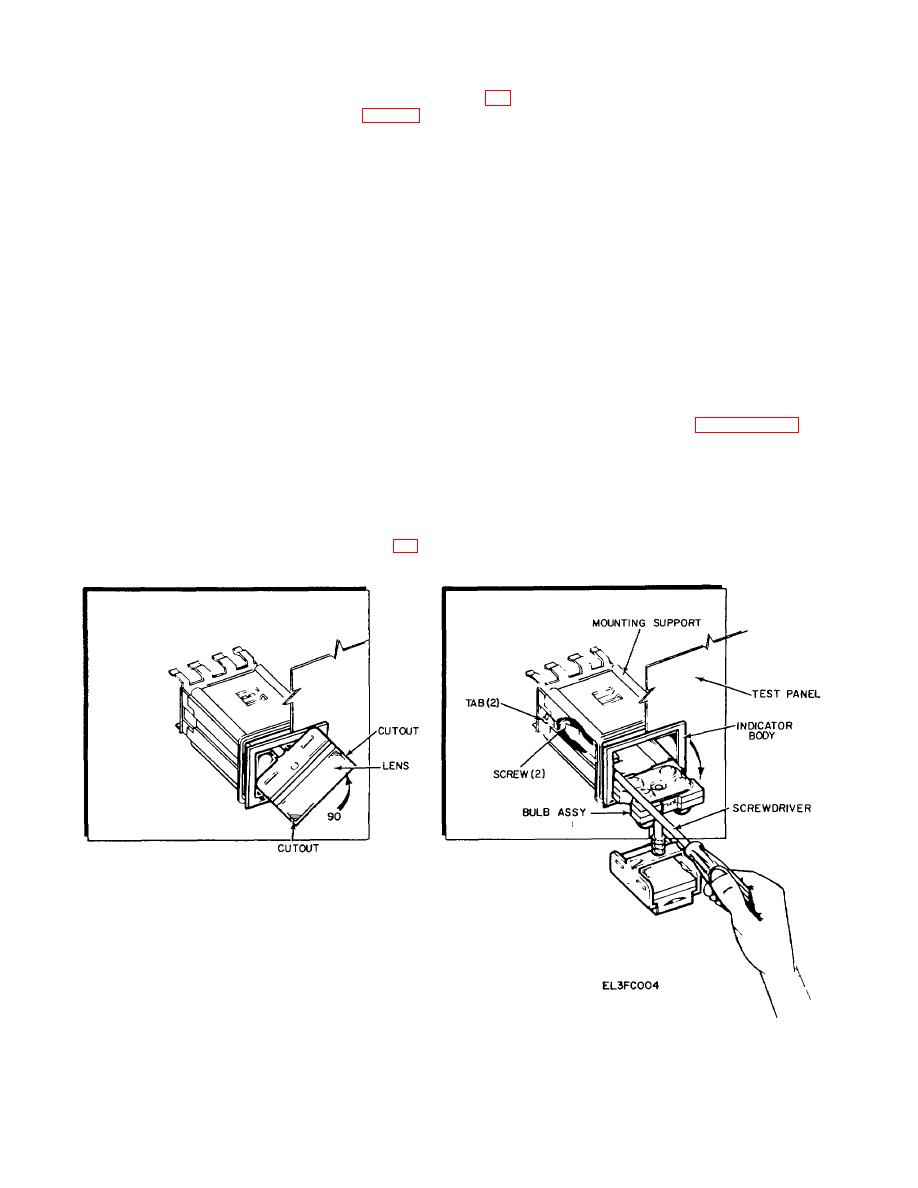
Figure 3-2. Replacement of indicator lamp assembly. |
|
||
| ||||||||||
|
|
 TM 11-6760-238-24
(27) and tighten setscrews (p/o 26).
t. Removal of lndicator Lamp Assembly (fig. 3-2)
(1) Position indicator body m test panel (2).
(2) Slide mounting support over indicator
NOTE
body and secure by tightening the two screws loosened
Removal and replacement instructions given in step t
in step t(4) above
and u below will be used for indicator lamp assemblies
(3) Push bulb assembly into indicator body
A2 (A3), A3 (24), A5 (10), A6 (11) A7 (12), and A9 (25)
and rotate lens 90 degrees clockwise to secure lens to
NOTE
indicator body.
Indicator lamp assemblies (11) and (12) have a plate and
v. Replacement of test panel. Position test panel
spacer assembly (22) that clips in. This assembly should
(2) in case (3) and secure with hardware removed in step
be removed and kept for reassembly purposes if either
a above.
of these subassembhes (11) or (12) are to be replaced.
3-9. DS3, DS4 or DS5 Light Source Focus
(1) Unsolder and tag all wires connected to
Adjustment
the indicator lamp assembly.
(2) Insert fingernails in cutouts m lens and
(fig. 3-)
pull lens away from indicator body.
The focusing adjustment procedure for each of the three
(3)
Rotate
lens
90
degrees
light sources on the test panel is as follows:
counterclockwise, push in slightly to remove tension on
a. Connect power cable W1 of LS-78A between
index key, and pull complete bulb assembly to stop of
POWER connector J2 on test panel and power source.
indicator body.
b. Loosen the two hex-nut setscrews mounting the
(4) Using screwdriver, loosen two screws on
lens barrel in position, (refer to paragraph 3-11a).
inside of indicator body by rotating counter clockwise
c. Carefully begin to tighten one of the setscrews
until tabs are loose and free mounting support
while manipulating the lens barrel in and out until it is felt
(5) Slide mounting support from test panel
that the screw is engaged in one of the threads on the
(2) direction of arrow.
lens barrel. The lens barrel may now be screwed in or
out into final adjustment.
(6) Remove indicator body from test
panel (2).
a. Replacement of Indicator Lamp Assembly (fig
Figure 3-2. Replacement of indicator lamp assembly.
3-9
|
|
Privacy Statement - Press Release - Copyright Information. - Contact Us |
