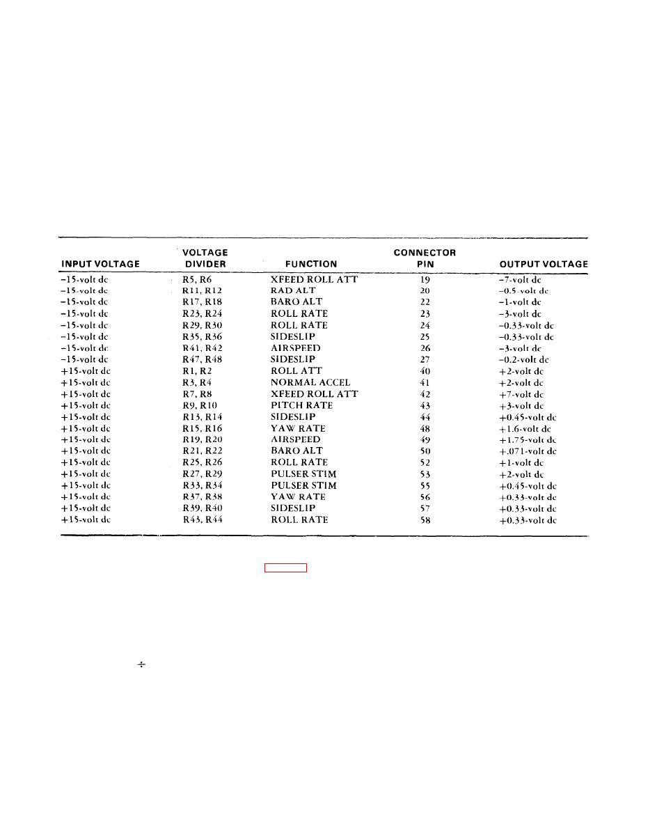
 |
|||
|
|
|||
|
|
|||
| ||||||||||
|
|
 TM 55-4920-430-13
(2) With +15 vdc applied across resistor 68 to Q1, the control panel simulation voltage at pin 12
is +12-volt dc.
(3) With +15-volt dc applied to resistors R49 and R50, the airspeed output at pin 13 is +0.31 volt
dc.
(4) With +15-volt dc applied to resistors R51 and R52, the airspeed output at pin 14 is +0.12-volt
dc.
(5) With +15-volt dc applied to resistors R53 and R54, the airspeed output at pin 18 is +0.21-volt
dc.
(6) With +15-volt dc applied across resistor R64 to pin 6, the inverting input of op-amp U2, the
roll detent voltage at pin 33 is -7-volt dc.
b. Step Dc Voltage Circuits.
(1) Resistors R55 thru R60, capacitor C1, and amplifier U2, provide 0.1 ma current. This current
is used as a self-test input signal for pitch, roll, and yaw servo simulators.
(2) With a -15-volt dc input, the output of voltage divider R55/R56 is -l-volt dc. The current
thru resistor R57 is 1 ua. This current is balanced by the current thru resistor R59, which is also 1 ua.
This current produces a +0.020-volt dc servo drive feedback voltage at pin 10. The current thru R60 is
+0.020-volt dc
200 ohms = +0.1 ma. The current through the load resistance between pin 34 and pin
10 is the sum of the currents thru R59 and R60.
d. Continuity Circuit.
(1) The continuity test circuits includes a resistance bridge, voltage comparator, and lamp di-
vider.
1-20
|
|
Privacy Statement - Press Release - Copyright Information. - Contact Us |
