 |
|||
|
|
|||
|
Page Title:
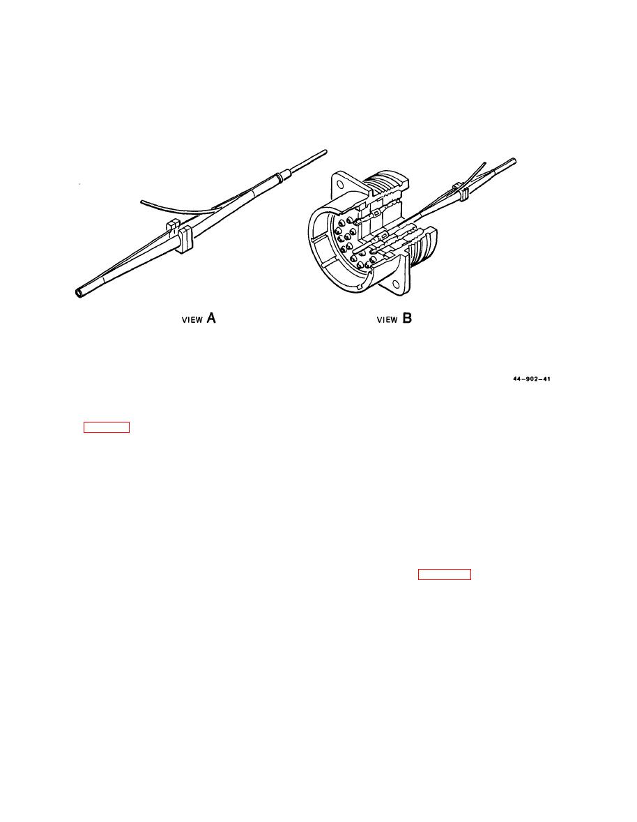
Figure 8-14. Contact Pin Insertion Tool Loading |
|
||
| ||||||||||
|
|
 ARMY TM 5-6675-309-14
MARINE CORPS TM 08840A-14/1
with sockethead screw key. Turret should
now index easily without binding.
tool, and positioner.
(c) Press trigger and spring-loaded turret will
(2)
Crimping tool MS3198-1, positioner MS3198-
snap out to indexing positions.
6P assembly.
(d) The turret has three positions which are
NOTE
color coded and marked with the applicable
The tool handles must be fully opened
contact size. Rotate the turret until the
when inserting the positioner, and when
correct position is lined up with the index
changing the selector positioner.
mark on the positioner.
(a) To install the positioner, place positioner in
(e) Push the turret into the positioner until it
bayonet socket at the back of the tool.
snaps into the locked position.
(b) Push positioner in and rotate 90 degrees
clockwise until locked in position.
ing operation as follows:
(3) Crimping tool MS3191-1, positioner MS3191-
(a)
Tool must be in open position. Close han-
9T assembly.
dles to trip ratchet and then release pres-
sure.
NOTE
(b)
Remove safety clip wire from selector con-
The tool handle must be fully opened
trol.
when inserting the positioner and when
Turn selector control in complete revolu-
(c)
changing the selector position.
tions until correct selector number is visible
(a) To install the positioner, depress the trigger
in the selector number window.
to release turret to the indexing positioner.
Tool is now ready for use. Replace safety
(d)
(b) Position the positioner over the retaining
clip wire.
ring on the back of the tool. Make certain
Insert the stripped wire into the contact
(e)
the positioner is seated on the tool; then
until end of wire can be seen through the
secure the 9/64-inch socket head screws
|
|
Privacy Statement - Press Release - Copyright Information. - Contact Us |
