 |
|||
|
|
|||
|
Page Title:
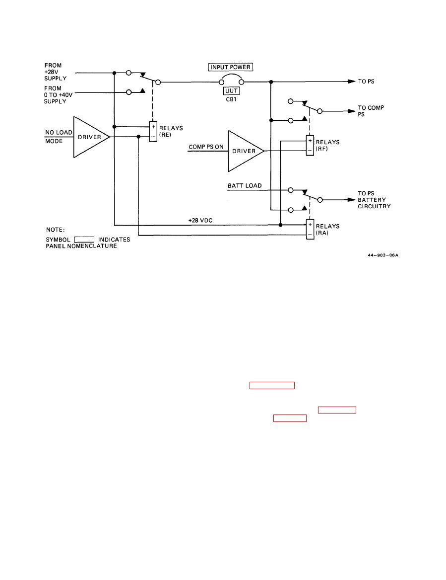
Figure 6-3. Power Supply Test Set Input Power Switching to the UUT |
|
||
| ||||||||||
|
|
 ARMY TM 5-6675-309-14
MARINE CORPS TM 08840A-14/1
k. At the end of the 2-second interval measured by
switch can be tested under no-load conditions, and the
PS battery charging circuitry can be tested. Testing the
the 2-second timer, if the UUT has not crowbarred or
PS battery charging circuitry is accomplished by using 0
turned itself off by its undervolt detection circuitry, the
PSTS will turnoff power to the UUT. This turnoff is
to +40V, 20-amp input power with the PSTS MODE
accomplished by fail detection circuitry which trips a
switch set in the NO LOAD position. Then, with
200-mA circuit breaker. The 200-mA circuit breaker is
INPUT POWER UUT circuit breaker closed, the input
ganged with the INPUT POWER UUT circuit breaker
power is routed directly to PSTS connector J6 and to
so that both breakers trip. When the PSTS 2-second
connector J7 through relay RA (RA is energized to the
timer causes such a shutdown, the OVERLOAD FAIL
closed-contact state by the MODE switch being in NO
switch-indicator lights, indicating that the UUT failed
LOAD position). The input power is also routed to the
the overload testing.
contacts of two other relays within the group labelled
RB in figure FO-1. The normally open side of the
l. Overtemperature protection is activated through
contacts of each of these relays is connected, respec-
overtemperature sensing circuitry. If internal tempera-
tively, to a 1-amp resistive load and to a 4-amp resistive
ture reaches 160F, a 1-minute timer will be activated.
load (labelled resistive loads in figure FO-1). The circui-
At the end of the 1-minute interval, the POWER
try is shown in figure 6-4.
SUPPLY TEST SET OVERTEMP indicator will light
and all loads will be removed from the UUT.
n. PSTS self-test is accomplished when the SELF-
TEST switch is placed in one of its active positions (any
m. When the MODE switch is in the NO LOAD
position except OFF).
position, any function selected by the FUNCTION
|
|
Privacy Statement - Press Release - Copyright Information. - Contact Us |
