 |
|||
|
|
|||
|
Page Title:
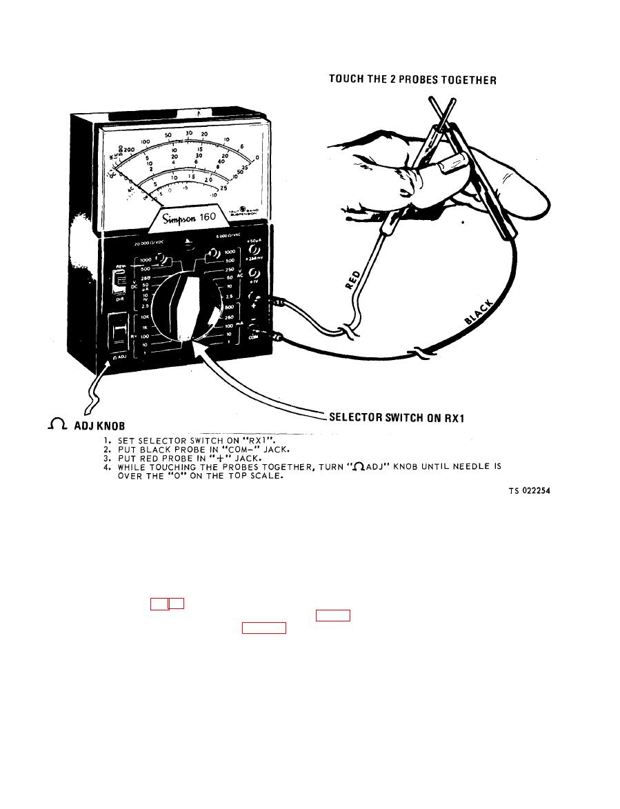
Figure 7-4. "Zeroing" the Simpson 160 meter. |
|
||
| ||||||||||
|
|
 TM 5-6625-2691-13&P
or 7-4).
NOTE
NOTE
If the needle will not "zero", replace the batteries. If
Failure to do the following steps can damage the
the needle still will not "zero" after replacing the bat-
teries, turn the meter in for repair.
(2) Disconnect the circuit being tested.
b. Continuity Tests. Continuity tests are made to
(3) Connect the meter probes to both terminals of
check for breaks in a circuit (such as the switch, light
the circuit being tested. (The TS-352B/U is illustrated
check, do the following steps:
same way with all three multimeters.)
(1) Set up and "zero" the multimeter (figs. 7-2,7-3
|
|
Privacy Statement - Press Release - Copyright Information. - Contact Us |
