 |
|||
|
|
|||
|
Page Title:
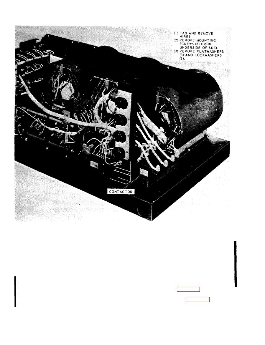
Figure 5-7. Contactor, removal and installation. |
|
||
| ||||||||||
|
|
 TM 5-6625-2691-13&P
iliary contact (K1-4) will open as soon as the power
5-12. Contactor
poles all close. If this contact does not open, the
a. Model A427 Contactor. This contactor, a
coil will draw excessive current, and could burn-
three pole, normally open with 24 VDC coil. It is
out. Also, if the auxiliary contact K1-4 opens
capable of switching and carrying the rated load of
before the power contacts close (or if K1-4 is al-
the test set. The nominal resistance of the coil is
ways open), the power contactor will not close. In
12 OHMS.
this situation, since the fans are not running, the
b. Model A427B Contactor. This contactor has
unit will shut down, and lock-out after about (5)
three normally open power poles and one each
seconds.
normally open and normally closed auxiliary con-
trol contacts. The contactor coil is nominal 24
contactor.
VDC with approximately 2 OHMS resistance. The
relay is designed so that the normally closed aux-
the contactor.
5-8 Change 1
|
|
Privacy Statement - Press Release - Copyright Information. - Contact Us |
