Home
Download PDF
Order CD-ROM
Order in Print
Figure 5-1. Processor, Vibration Signal with Troubleshooting Test Points
Section IV. REMOVAL AND REPLACEMENT OF MAJOR COMPONENTS AND ASSEMBLIES
Maintenance Manual For Control Unit, Alarm Set C-9412/Fss-9(V) -4
Page Navigation
22
23
24
25
26
27
28
29
30
31
32
TM
5-6350-264-14&P-4
NAVELEX
EE
181-AA-OMI-050/E121
DT546
M9442
TO
31S9-2FSS9-1-4
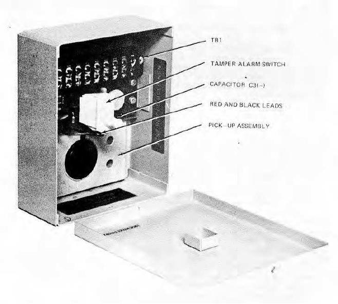
Figure
5-2.
Detector,
Vibration
Signal
with
Troubleshooting
Test
Points
5-21