
TM 5-6350-264-14&P-3
NAVELEX EE 181-AA4)MI-040/E121 R1860 M9443
TO 31S9-2FSS9-1-3
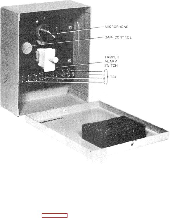
Figure 5-2. Receiver, Ultrasonic Motion Sensor with Troubleshooting Test Points
Section III. GENERAL MAINTENANCE
on the gain control in the Receiver and the sensitivity
5-4. MAINTENANCE ACTION. The extent of direct
control in the Processor. Inspection only is made on the
and general support maintenance is governed by the
housings. Periodic testing of the Passive Ultrasonic
Maintenance Allocation Chart (MAC), Appendix B. The
Sensor is not scheduled because the J-SIIDS is
MAC provides for on-site test and replacement of the PC
maintained in continuous operation.
boards in both the Processor and Receiver. On-site
adjustment is made
5-18