
TM 5-6350-264-14&P-3
NAVELEX EE 181-AA-OMI-040/E121 R1860 M9443
TO 31S9-2FSS9-1-3
Table 5-1. Troubleshooting Procedures - Continued
Trouble
Probable cause
Corrective action
4. (cont)
b. (cont)
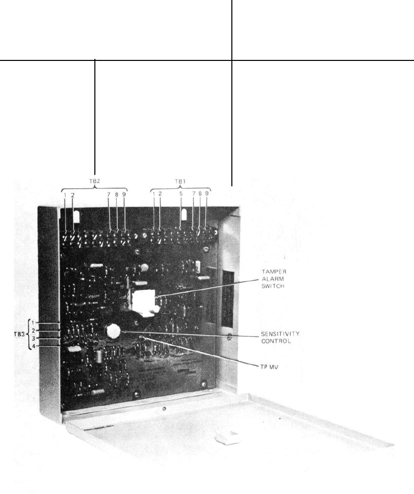
(2) To replace the PC board, orient
the board so that terminal strip
TB1 is adjacent to the conduit
connections. Secure the PC
board to the housing with screws.
Attach the wires to TB1.
(3) Adjust the gain control per steps
in TM 5-6350-264-14/1.
Figure 5-1. Processor, Ultrasonic Motion Sensor with Troubleshooting Test Points
5-17