 |
|||
|
|
|||
|
Page Title:
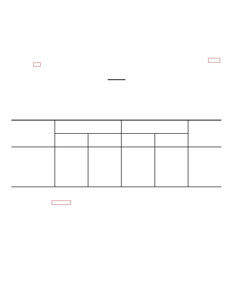
Table 3-6. Cable Assembly Installation |
|
||
| ||||||||||
|
|
 TM 11-7010-201-40-1/ET821-AA-MMI-010/E154 MTS/TO 31S5-2TSQ73-2-1
b. Replacement. Replace cable assembly as follows:
(1) Slide cable assembly printed wiring boards into card guides and insert in connector slot in card racks (refer to
table 3-7).
(2) Slide card retainers back to original position until retainer detent locks.
(3) Carefully push loops of cable assemblies into recess between front panel and MTS frame as shown in figure
(4) Place cable supports in position on end of card racks and secure each with two screws.
CAUTION
Ensure that the cable assemblies are properly tucked into the recess between the front
panel and the frame to avoid damage when retracting the MTS into the case.
(5) Retract MTS into case following procedure of paragraph 3-11.
Table 3-6. Cable Assembly Installation
From
To
Reference designator
Bay
Slot
Bay
Slot
Part number
W552
2
03
3
02
10284102-6
W553
2
04
3
03
10284102-7
W554
2
05
3
01
10284102-8
W556
1
47
2
01
10284709-6
3-1 5. Cable Assembly W556 Removal and Replacement. Perform the following procedure to remove and replace
cable assembly W556 (figure 3-9).
a. Removal. Remove cable assembly W556 as follows:
(1) Extend MTS from case following procedure of paragraph 3-11.
(2) Remove two screws securing cable support to right-hand digital card rack (bay 2).
(3) Remove cable support from right-hand digital card rack.
(4) Carefully push cable assemblies W552, W553, and W554 aside.
3-23
|
|
Privacy Statement - Press Release - Copyright Information. - Contact Us |
