 |
|||
|
|
|||
|
Page Title:
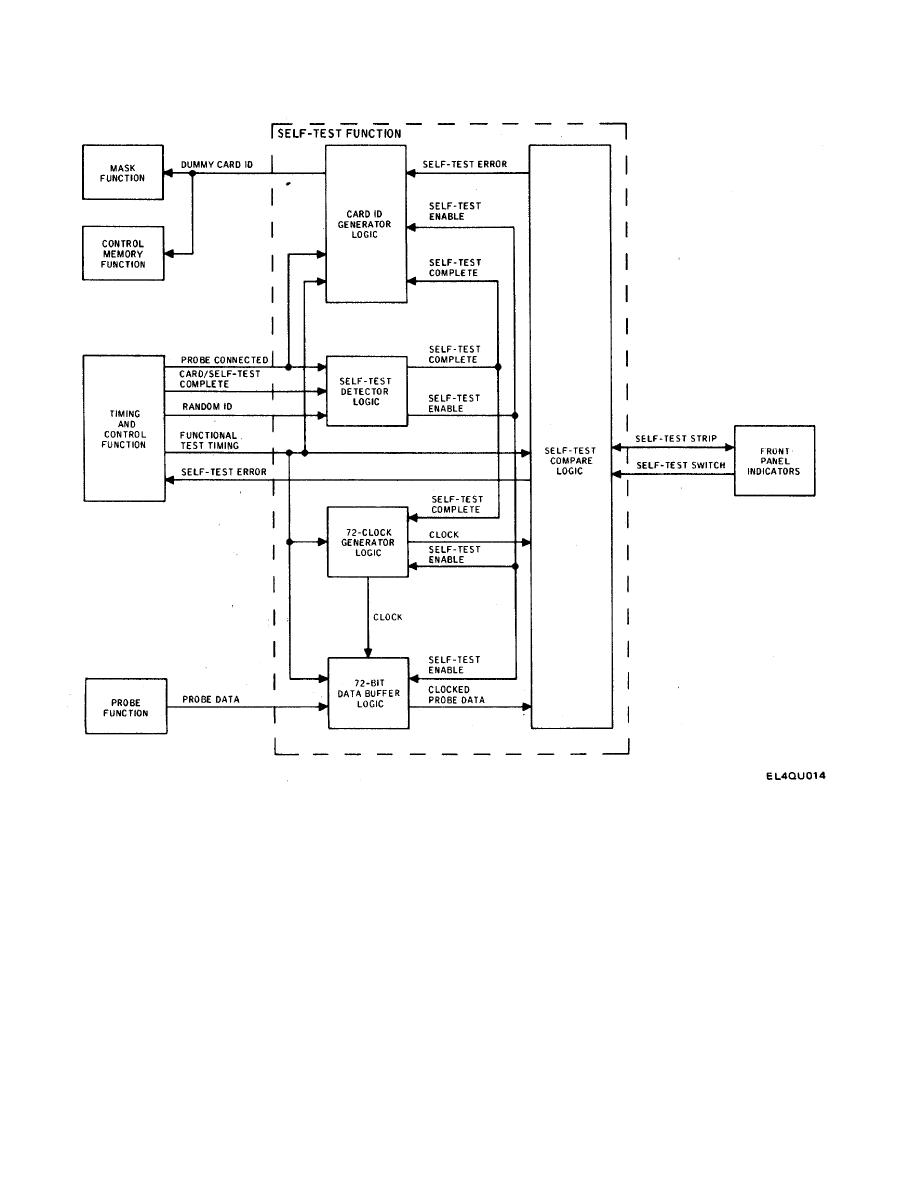
Figure 2-7. Self-Test Function Block Diagram |
|
||
| ||||||||||
|
|
 TM 11-7010-201-40-1/ET821-AA-MMI-010/E154 MTS/TO 31S5-2TSQ73-2-1
Figure 2-7. Self-Test Function Block Diagram
If an error is detected, the GO indicator goes out and the NO-GO indicator remains on. The self-test error signal causes
the self-test routine to loop on the card ID where the failure occurred. To get out of this loop, the operator must press the
SELF-TEST switch on the front panel. If the self-test procedure is completed with no errors detected, the NO-GO
indicator goes out and the GO indicator remains, on. When the self-test is completed, the timing and control function
applies the card/self-test complete signal to the self-test detect logic. The self-test detect logic then generates an internal
self-test complete signal and stops the self-test function.
2-20
|
|
Privacy Statement - Press Release - Copyright Information. - Contact Us |
