 |
|||
|
|
|||
|
Page Title:
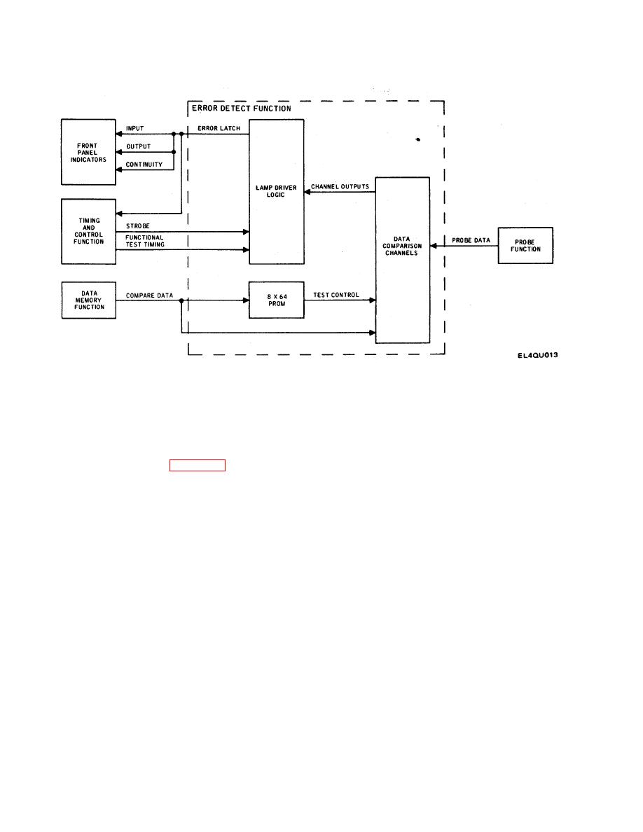
Figure 2-6. Error Detect Function Block Diagram |
|
||
| ||||||||||
|
|
 TM 11-7010-201-40-1/ET821-AA-MMI-010/E154 MTS/TO 31S5-2TSQ73-2-1
Figure 2-6. Error Detect Function Block Diagram
If no error is present during either strobe, no front panel error indicator lights.
2-12. Self-Test Function. The self-test sequence is initiated by connecting the test set probe assembly to terminal
board TB1l1 (self-test strip) on the MTS front panel. The timing and control function transfers the random ID signal to the
self-test detector logic (see figure 2-7). The self-test detector logic interprets the random ID signal as the self-test
function. The probe-connected signal enables the card ID generator logic. The card ID generator logic is a six-bit binary
counter. The output of the card ID generator logic is a dummy card ID corresponding to one of the MTS-testable cards.
The output is applied to the control memory function as if the output were a true card ID. The MTS then cycles through
state timing to state 7 as if an actual card were being tested. At state 7, the dummy card ID is presented to the control
memory function. This action initiates the first bit of the corresponding test pattern. The probe data (72 lines) from the
probe function is loaded by the functional test timing signal into the 72-bit data buffer logic. The clock signal from the 72-
clock generator logic serially clocks the probe data (test pattern) into the self-test compare logic. The probe data is
clocked with the clocked probe data signal. After the 72 bits of data are dumped into the self-test compare logic, the
functional test timing signal loads the next bits of the test pattern into the 72-bit data buffer logic. This sequence is
repeated until a complete set of test patterns for that card ID is stored in the self-test compare logic. Then, the sum of
the test pattern data is compared with the stored data. If no error occurs the card ID generator logic is advanced by the
functional test timing signal to the next dummy binary coded card ID and the test sequence for that card ID is initiated.
This continues until all data for all of the testable cards is processed and error-checked.
2-19
|
|
Privacy Statement - Press Release - Copyright Information. - Contact Us |
