 |
|||
|
|
|||
|
Page Title:
Table 3-1. Front Panel Controls and Indicators-continued |
|
||
| ||||||||||
|
|
 TM 11-6625-3024-14/EE641-AC-MMA-010/E154 SYSEX/TO 33AA50-5-1-1
Table 3-1. Front Panel Controls and Indicators (Continued)
Function
Control/Indicator
TRANSPORT
Provides +28 Vdc power to the transport. The
ECR-10
Exerciser SYSTEM ON/OFF power switch must be
460-9101
ON before transport power can be enabled.
Note
A current sense loop or a 5 amp rated
ammeter must be inserted in the
TRANSPORT CURRENT jacks before
transport power can be enabled.
WRITE DATA
Note
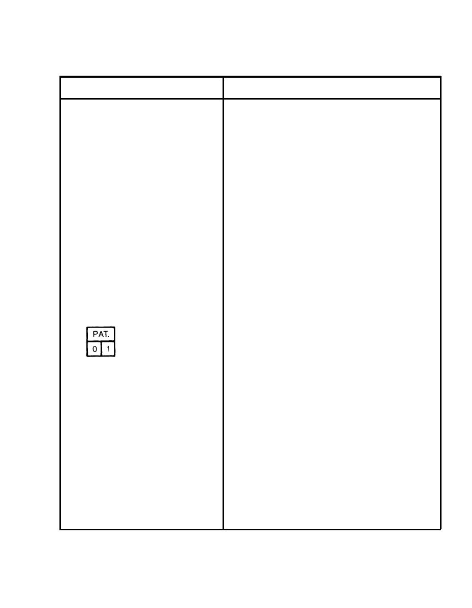
The Write Data controls are push-ON
and push-CHANGE, three-position
pushbutton switches. The lighted portion
of the switch indicator indicates the
enabled function.
Selects the write data to be written on tape. When
PAT. (Pattern) is lighted a data pattern will be
written on tape. When "0" is lighted a logic 0 will be
written on tape. When "1" is lighted a logic 1 will be
written on tape. The nine indicator switches
(Indicator Switches)
provide write data selection for tracks 0 through 7
and Parity. A test jack under each indicator is
provided to monitor each write data track, parity
track, and the write data clock.
A test jack is provided under each PAT./ 0 / 1
Grid, 0 through 7, P and CLK
indicator to monitor each write data track, parity
Test Jacks
track and the write data clock. The GND test jack is
used as return for all write data test jacks.
Selects all tracks at once (except parity track) to
ALL O
logic O write data. The white portion (0) of the
Switch (white)
WRITE DATA indicators for all tracks (except parity
track) will light.
3-7
|
|
Privacy Statement - Press Release - Copyright Information. - Contact Us |