 |
|||
|
|
|||
|
|
|||
| ||||||||||
|
|
 TM 11-6625-2975-12
2-4. OPERATING PROCEDURES. (CONT)
1. Using DATA ENTRY keys, enter a marker beacon interference-type signal into test set.
2. Repeat step 1 using a different frequency interference -type signal (if required).
PERCENT MODULATION ADJUSTMENT
NOTE
In preset condition for each mode of operation, the percent modulation is automatically
set to the accepted standard. The percent modulation can be varied from standard in
both directions In 0.1-percent steps. Table 2-13 lists percent modulations for preset
conditions and variable range with respect to each mode of operation.
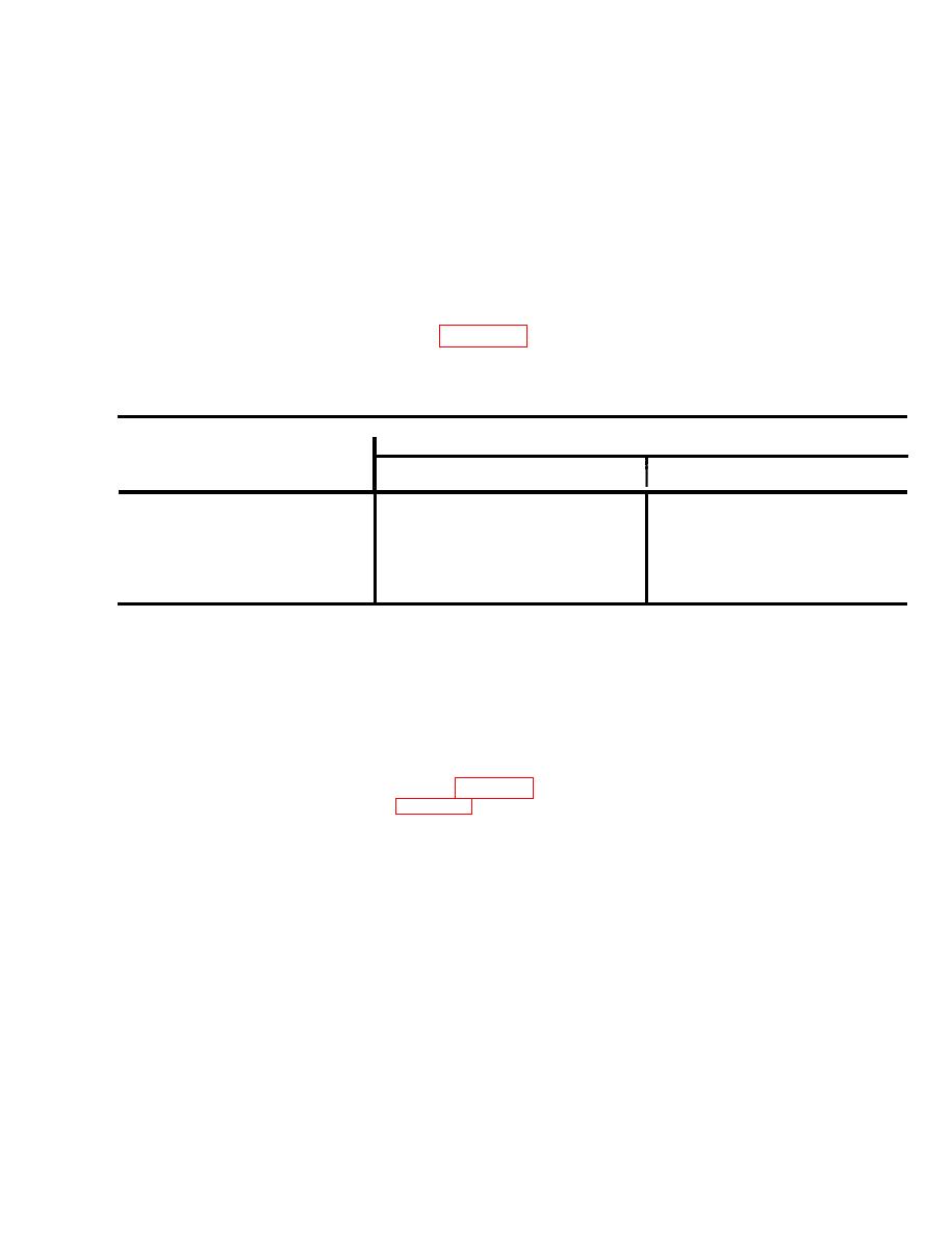
TABLE 2-13. PERCENT Modulation CHART
I
PERCENT MODULATION
MODE
VARIABLE RANGE
PRESET CONDITION
30.0
10.0 to 35.0
VOR
20.0
5.0 to 40.0
Localizer
10.0 to 80.0
40.0
Glide slope
95.0
90.0 to 97.0
Marker beacon
NOTE
In Iocalizer and glide slope modes of operation, DDM must be set to 0.000 before
percent modulation can be varied.
1020 Hz audio tone amplitude modulation is a fixed 30 percent in VOR and Iocalizer
modes. 1020 Hz tone Is not present in glide slope mode.
Enter selected rf carrier frequency from table 2-11 into test set (FREQUENCY/MODE
1.
SELECTION, steps 1 through 6, page 2-16).
NOTE
In marker beacon mode, percent modulation is displayed in RDL/DDM/MOD display
2-41
|
|
Privacy Statement - Press Release - Copyright Information. - Contact Us |