 |
|||
|
|
|||
|
Page Title:
TABLE 2-8. MODE DISPLAY INDICATORS |
|
||
| ||||||||||
|
|
 TM 11-6625-2975-12
2-2. CONTROLS AND INDICATORS. (CONT)
Associated with FREQUENCY display is MODE display, which consists of five indicators. Table 2-8
shows individual indicator functions.
TABLE 2-8. MODE DISPLAY INDICATORS
INDICATOR
FUNCTION
Indicates
self-test mode has been selected.
SELF TEST
Indicates
selection of marker beacon mode of operation.
MB
Indicates
selection of VOR mode of operation.
VOR
Indicates
selection of Iocalizer mode of operation.
LOC
Indicates
selection of glide slope mode of operation.
GS
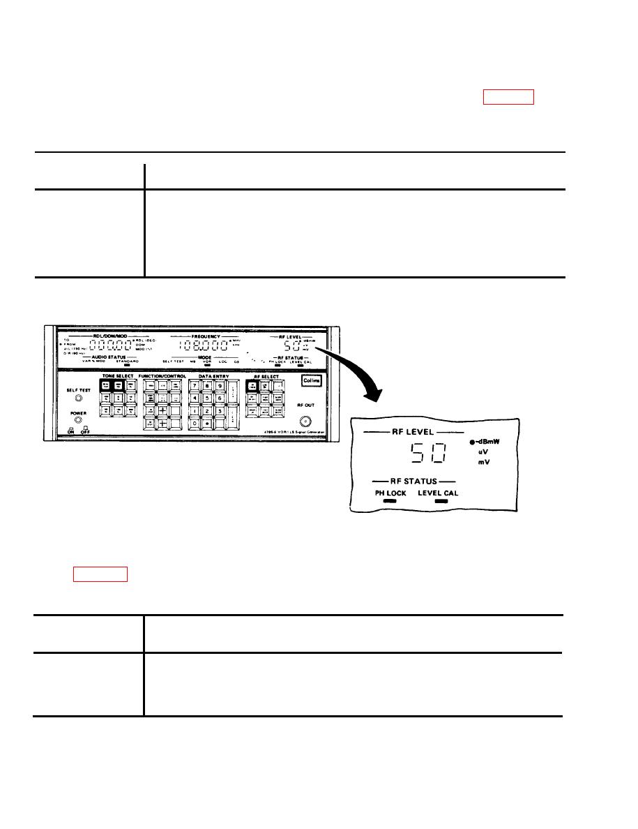
RF LEVEL DISPLAY
EL9LX016
RF LEVEL display provides a readout of rf output signal level in decibels, microvolt, or millivolts. In
addition to the three-digit, seven-segment display, there are three indicators associated with the
display. Table 2-9 shows individual indicator functions.
TABLE 2-9. RF LEVEL LED INDICATOR FUNCTIONS
INDICATOR
FUNCTION
-dB mW
Rf output reading in decibels.
V
Rf output reading in microvolt.
Rf output reading in millivolts.
mV
2-8
|
|
Privacy Statement - Press Release - Copyright Information. - Contact Us |
