 |
|||
|
|
|||
|
|
|||
| ||||||||||
|
|
 TM 11-6625-2885-30/NAVAIR 16-35TS3614-2
RF
OUTPUT
LEVEL
ADJUSTMENT
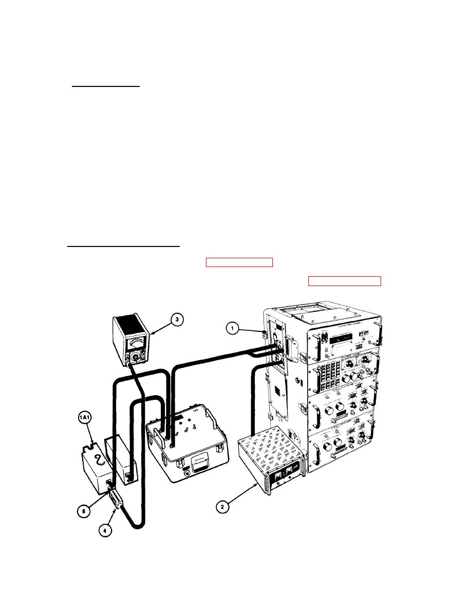
3-21.
a. Test Equipment. Use the following test equipment or equivalent to
adjust the RF output level:
TS-3615/ALQ-136(V)
BTS (1)
PP-1104/G
Power Supply (2)
HP 435A
Power Meter (3)
HP 8481A
Power Sensor (4)
N female to SMA male (You may use
Adapter (5)
NF-TNCM and TNCF-SMAM adapters.)
CAUTION
After unfastening video front panel assembly, it
is still secured to the case by wires from the
power supplies. Remove the video front panel
assembly carefully.
Test Connections and Conditions.
b.
(1) With FLTS connector as in paragraph 3-8, using adapter, connect Power
Sensor to Transmitter Assembly 1A1J2.
(2) Remove video assembly front panel from case as in paragraph 3-22a.
Remove circuit card retaining plate for access to adjustment.
|
|
Privacy Statement - Press Release - Copyright Information. - Contact Us |
