 |
|||
|
|
|||
|
|
|||
| ||||||||||
|
|
 REPLACEMENT OF PRINTED CIRCUIT BOARDS (Continued)
REMOVAL (Continued)
(2) Loosen four captive screws (1) on the front of RF Modulation Assembly
1A3/1A4 and retract from the BTS cabinet.
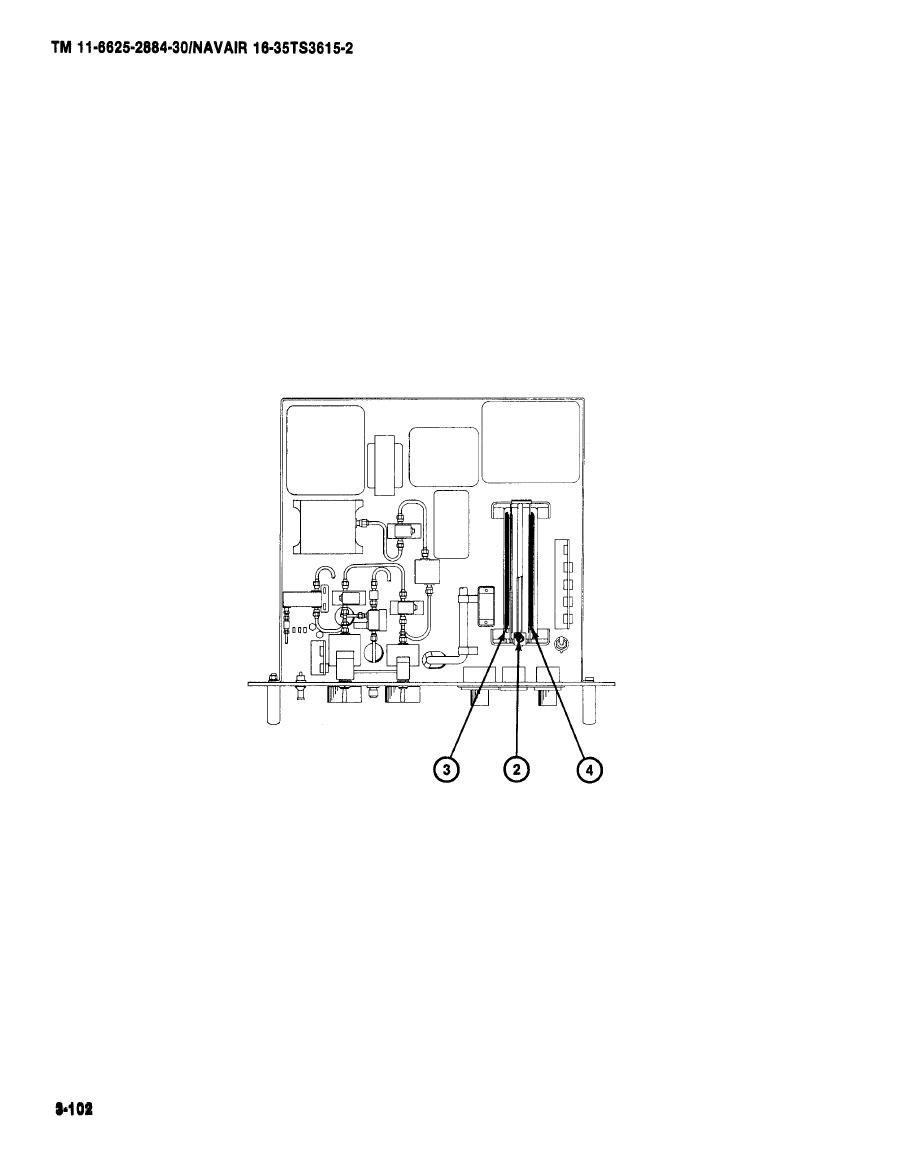
(3) Using a screwdriver, rotate the captive screw (2) counterclockwise
until free and rotate lid of enclosure to the rear. Both circuit
cards are now ready for removal.
(4) Grasp circuit card 1A3/1A4-A1 (3) or 1A3/1A4-A2 (4) and pull cir-
cuit card directly out of jack.
TOP VIEW
|
|
Privacy Statement - Press Release - Copyright Information. - Contact Us |