 |
|||
|
|
|||
|
|
|||
| ||||||||||
|
|
 TM 11-6625-2884-30/NAVAIR 16-35TS3615-2
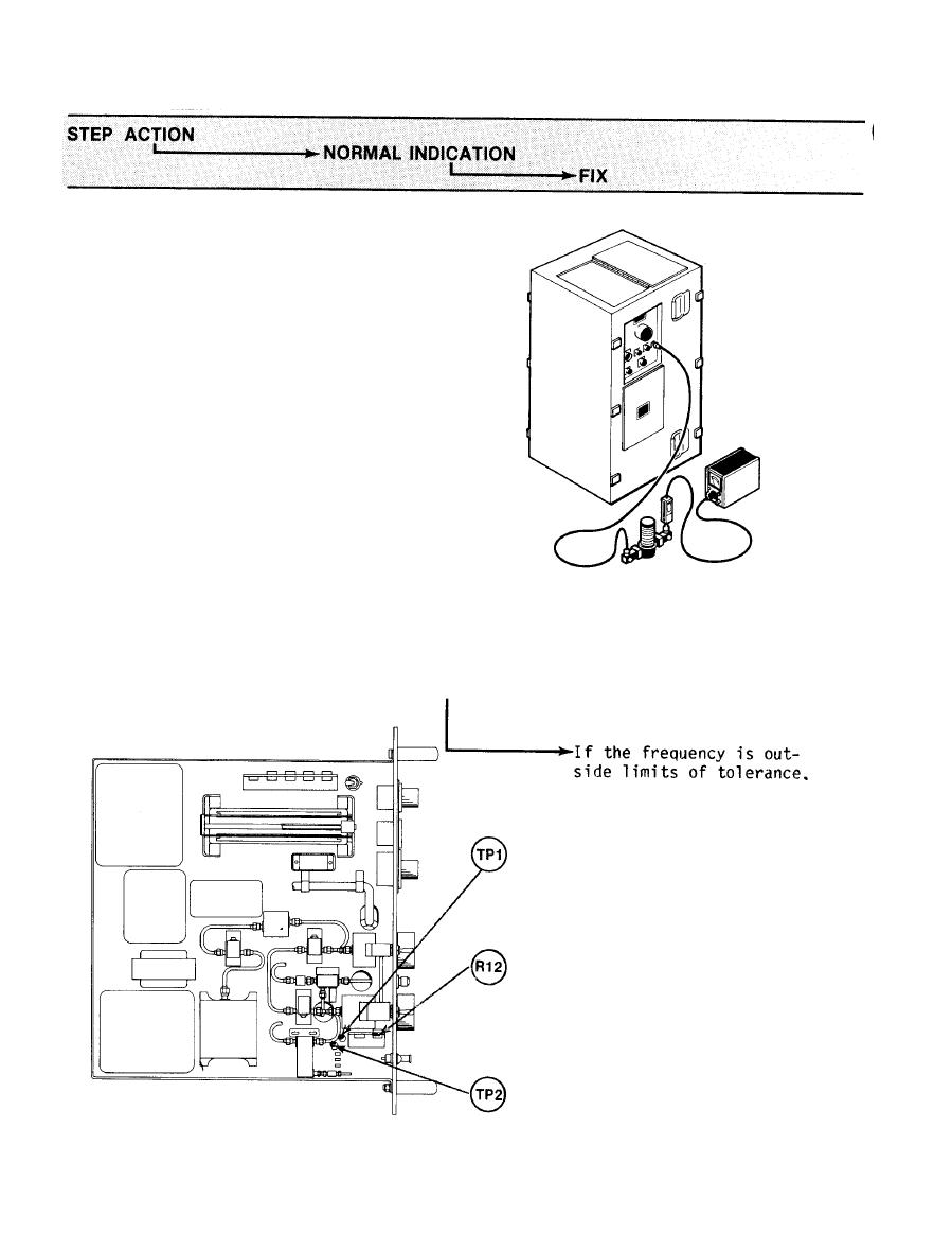
RF OUTPUT FREQUENCY CHECK (Continued)
Procedure.
e.
1.
Connect frequency meter
to CMBD RF jack J4 on
upper left side of BTS
cabinet.
Connect RF power meter
2.
sensor to the frequency
meter output.
3.
Set OUT SEL switch on
1A3 to CM, PRI selector
switch to VAR PRI. Set
1A4 PRI selector switch
to OFF.
4.
Tune RF frequency meter
for a dip in RF power as
observed on the power
meter, record dial read-
ing at which the dip
occurs as frequency F1.
Frequency = F1 O.1 GHz
(See (S) TM-11-5865-202-30 (U)
for values of F1, F2 and F3.)
perform the following
steps.
a.
Remove semi-rigid
connector from jack
J2 on rear of unit.
Disconnect frequency
meter from jack J4,
and connect to RF OUT
connector on front
panel of unit.
3-20
|
|
Privacy Statement - Press Release - Copyright Information. - Contact Us |