 |
|||
|
|
|||
|
Page Title:
RF Modulation Assemblies 1A3/1A4 |
|
||
| ||||||||||
|
|
 TM 11-6625-2884-30/NAVAIR 16-35TS3615-2
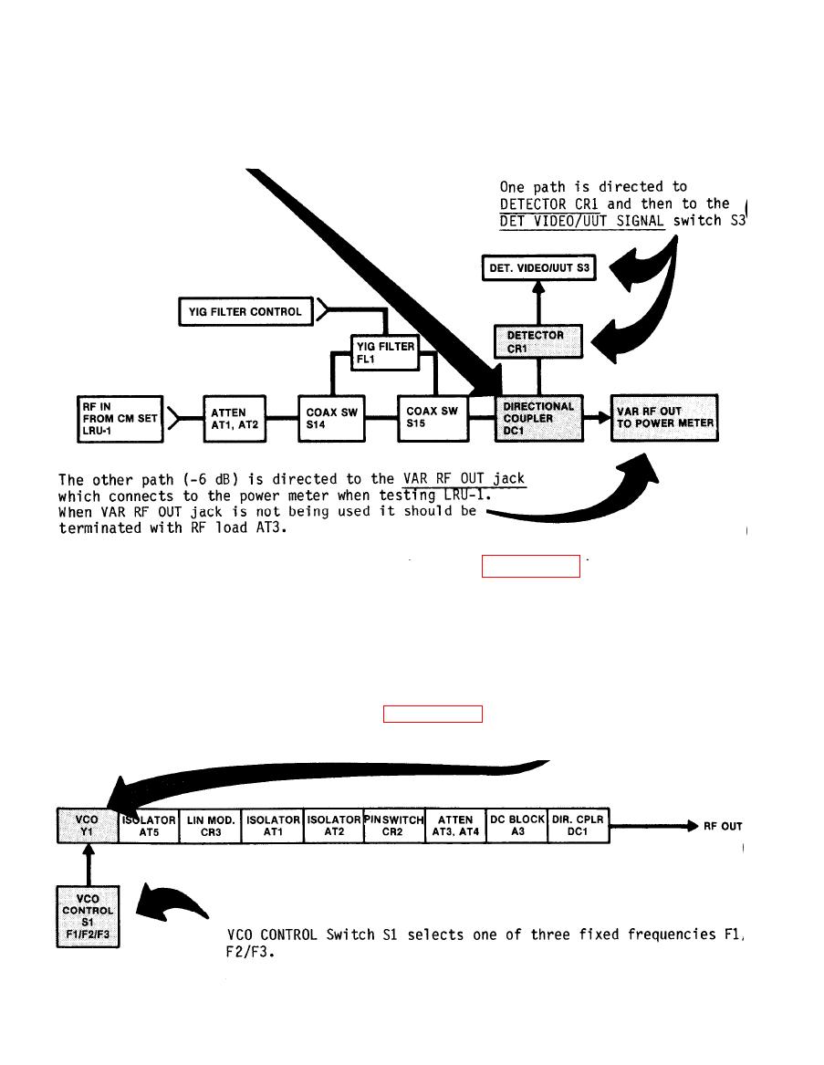
BLOCK DIAGRAM DESCRIPTION (Continued)
The RF signal from Coax Switch S15 is
split at DIRECTIONAL COUPLER DC1
c.
RF Modulation Assemblies 1A3/1A4. (Refer to figure FO-l. ) The
RF Modulation Assemblies are divided into three functional areas.
RF PATH (CW)
LINEAR MODULATION (CON SCAN)
PULSE MODULATION (A-W/A-F/B/VAR PRI)
(1) RF Path (CW). (Refer to figure FO-1.) The RF source
is a linearized voltage controlled oscillator VCO. (+17 dBm
output)
|
|
Privacy Statement - Press Release - Copyright Information. - Contact Us |
