 |
|||
|
|
|||
|
Page Title:
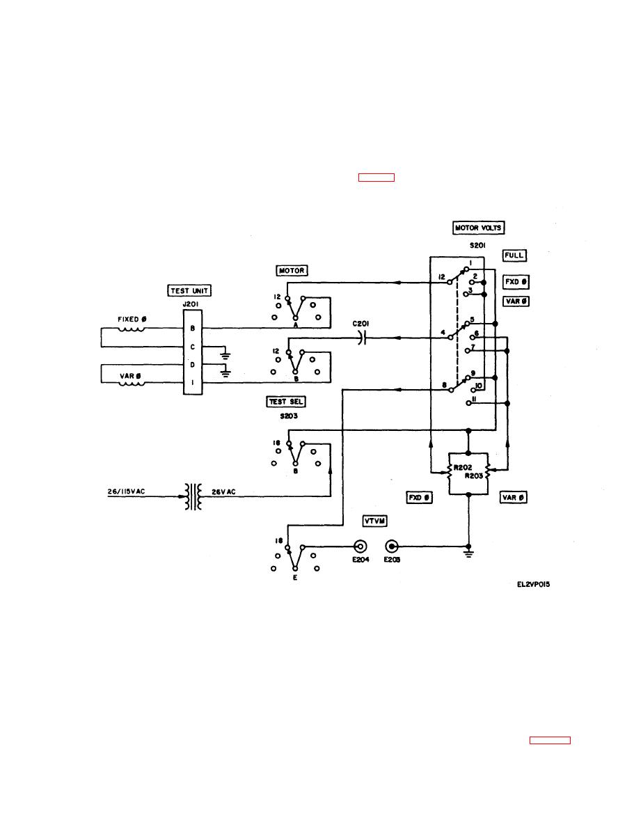
Figure 5-6. Low-inertia motor test circuit schematic diagram. |
|
||
| ||||||||||
|
|
 TM 11-6625-2843-14
in the stators of transmitter B201 or the control
transformer and, therefore, the input to the ser-
signal is induced in the transmitter stator and this sig-
voamplifier is at null. The dial reading of the indicator
nal is transmitted to the stator of the control
is then checked for correspondence with the setting of
transformer. A magnetic field is built-up across the
the transmitter dial.
stator which induces a voltage across the rotor of the
c o n t r o l transformer. This voltage is amplified by ser-
Low-Inertia
Motor
Test
Circuit
voamplifier A201 and applied at a suitable level to the
NOTE
variable-phase winding of the low-inertia motor. The
The low-inertia motor is part of a servoed in-
motor drives the rotor of the control transformer
dicator. The low-inertia motor test circuit
through a gear train through a proportional angle of
rotation. At this position, no voltages are induced with-
motor rotation. With MOTOR VOLTS switch S201 at
a. Direction Test. The direction test is enabled by
FXD 26 volts are applied to the fried-phase motor
TEST SEL switch S203 at MOTOR, and MOTOR
windings and to the VTVM binding posts. The FXD
VOLTS switch S201 at FULL. With this teat setup, 26
control may then be adjusted to the rated value of the
volts are applied to the fixed- and variable-phase wind-
fixed-phase motor winding. Similarly, with the
ings of the low-inertia motor. Capacitor C201, in the
M O T O R VOLTS switch at VAR VAR control R203
variable-phase line, introduces a 90-degree phase shift
adjusts the rated value of the variable-phase motor
between the two windings. The motor rotates and the
winding.
direction of motor rotation may be observed.
test is enabled by TEST SEL switch S203 at MOTOR
The indicator test circuit for transmitters (fig. FO-1) is
enabled by TEST SEL switch S203 at TRANS and
and is used to measure the voltage required to start
|
|
Privacy Statement - Press Release - Copyright Information. - Contact Us |
