 |
|||
|
|
|||
|
Page Title:
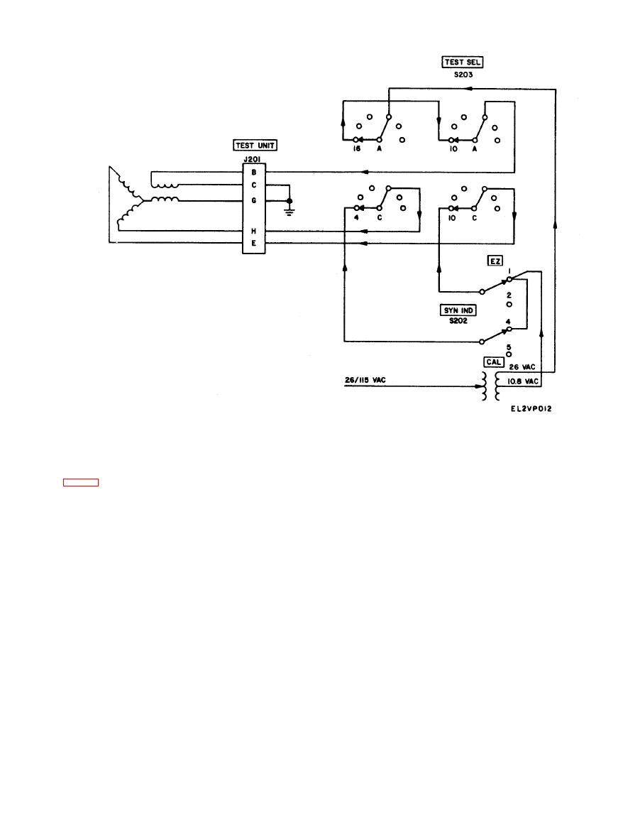
Figure 5-3. Electrical zero test circuit schematic diagram. |
|
||
| ||||||||||
|
|
 TM
11-6625-2843-14
B201 is displaced, a signal is induced in the transmit-
5-6. Transmitter Test
Circuit
for
Syn-
ter stator, and this signal is transmitted to the indica-
chronous Indicators
tor stator. A magnetic field is built-up across the in-
T h e transmitter test circuit for synchronous indicators
dicator stator which causes the rotor to turn to a
position that corresponds to that of the transmitter.
IND and SYN IND switch S202 at CAL. With this test
The dial reading of the indicator is then checked for
setup, the rotors of transmitter B201 and the indicator
correspondence with the setting of the transmitter dial.
under test are energized by 26 volts, and the stators are
connected back to back. When the rotor of transmitter
|
|
Privacy Statement - Press Release - Copyright Information. - Contact Us |
