 |
|||
|
|
|||
|
Page Title:
CHAPTER 5. DIRECT SUPPORT MAINTENANCE INSTRUCTIONS AND FUNCTIONING OF EQUIPMENT |
|
||
| ||||||||||
|
|
 TM 11-6625-2843-14
DIRECT
SUPPORT
MAINTENANCE
INSTRUCTIONS
AND
FUNCTIONING
OF
EQUIPMENT
S e c t i o n I. DIRECT SUPPORT MAINTENANCE INSTRUCTIONS
back shell can be unscrewed.
General
(2) Tag and unsolder wirea from all pins in shell of
Direct support maintenance is limited to the repair of
connector. Discard damaged connector.
the special purpose cables and power cords. Mainte-
(3) Insert and resolder all pins to proper pins of
nance beyond this level must be referred to depot for
r e p l a c e m e n t connector. Use insulation sleeving over
repairs.
connector pins.
Repair
of
Electrical
Cable
Assemblies
(4) Reinstall back shell of connector and reinstall
R e p a i r of electrical cables assemblies with defective
stress relief bar into place and tighten two screws.
connectors is accomplished as follows:
(5) Check for continuity between
connectors,
referring to cable wiring diagram.
(1) Loosen two screws on stress relief bar so that
Section Il. FUNCTIONING OF EQUIPMENT
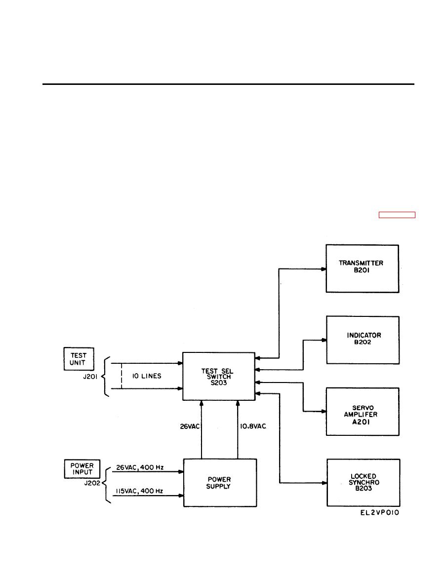
and an indicator teat circuit for checking simplified
5-3. Principles of Operation
synchro transmitters and differentials. See figure 5-1
a The test set consists of two main test circuits, a
for a functional block diagram.
t r a n s m i t t e r test circuit for testing synchro indicators
5-1
|
|
Privacy Statement - Press Release - Copyright Information. - Contact Us |
