 |
|||
|
|
|||
|
Page Title:
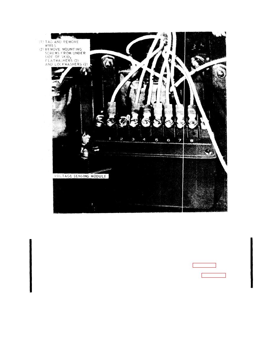
Figure 5-6. Voltage sensing module, removal and installation. |
|
||
| ||||||||||
|
|
 TM 5-6625-2691-13&P
TS 025342
Figure 5-6. Voltage sensing module, removal and installation.
of this module. With all wind and heat switches
this situation, the sensing module will allow the
closed, terminals 4 and 5 are connected together.
power transistor to conduct; thus pulling-in the
If any of these switches open for a period greater
power contactor (Kl). If the test set is incorrectly
than (5) seconds the power transistor will cease to
programmed for the level of a.c. input test voltage,
conduct causing power (contactor (K1) to drop-out.
the power transistor will not conduct and power
contactor (K1) will not pick-up. The Model A427B
voltage sensing unit.
Voltage Sensing Module also requires that all air
flow switches and over heat switches are closed to
the voltage sensing unit.
sustain unit operation. All of these switches are
series wired and connected across terminal 4 and 5
Change 1
|
|
Privacy Statement - Press Release - Copyright Information. - Contact Us |
