 |
|||
|
|
|||
|
Page Title:
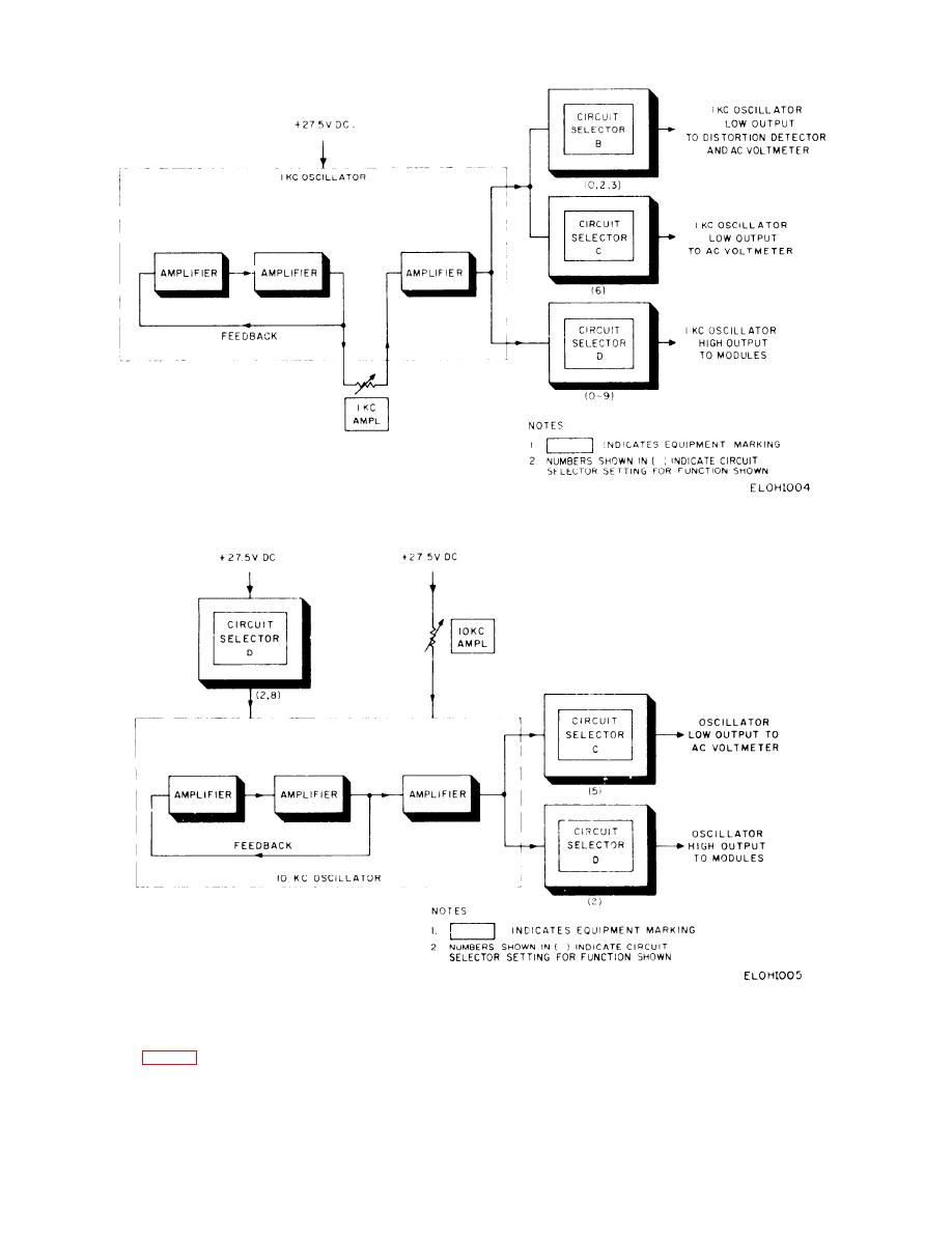
Figure 2-4. 1kHz oscillator circuit, functional diagram. |
|
||
| ||||||||||
|
|
 TM 11-6625-467-34
Figure 2-4. 1kHz oscillator circuit, functional diagram.
Figure 2-5. 10-kHz oscillator circuit functional diagram.
2-9. 3.975 MHz Oscillator Signal Paths
CUIT SELECTOR D (position 9) connects +27.5
volts dc to the LOW FREQ AMPL control, and CIR-
CUIT SELECT0R C (position 8) connects the LOW
The 3.975 megahertz oscillator produces a 3.975
FREQ AMPL control output to the oscillator. The
megahertz sine wave output signal. The oscillator
LOW FREQ AMPL control adjusts the oscillator
output appears at the 3 MC jack of the test set. CIR-
2-6
|
|
Privacy Statement - Press Release - Copyright Information. - Contact Us |
