 |
|||
|
|
|||
|
Page Title:
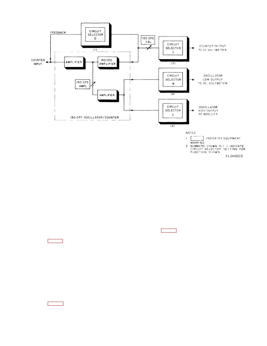
Figure 2-3. 150 Hz oscillator/counter circuit functional diagram. |
|
||
| ||||||||||
|
|
 TM 11--6625-467-34
Figure 2-3. 150 Hz oscillator/counter circuit functional diagram.
f o r testing the module circuits. CIRCIUIT S E -
various module inputs.
b. 150 Hz Counter. The 150 Hz counter is a selec-
LECTOR D, when set to position 2 or 8, supplies
o p e r a t i n g voltage to the oscillator. The 10 KC
tive amplifier circuit that measures the frequency
AMPL control adjusts the 10 kHz output amplitude.
of the 150 Hz oscillator in the sel-call module. For
In position 5, CIRCUIT SELECTOR C connects
counter operation, CIRCUIT SELECTOR D opens
the low oscillator output to the ac voltmeter circuit
the feed back loop and the circuit operates as a se-
for readout. CIRCUIT SELECTOR. in position 2,
lective amplifier. The 150 CPS CAL control adjusts
connects the high oscillator output to the module
the output amplitude of the counter circuit. CIR-
circuits.
C U I T SELECTOR C (position 3) connects the
c o u n t e r output to the ac voltmeter circuit for
2-8. 500 kHz FM Oscillator Signal Paths
readout.
2-6. 1 kHz Oscillator Signal paths
The 500 kilohertz frequency-modulated (fm) oscil-
lator produces a 500 kHz sine wave output for test-
ing the module circuits. The oscillator is capable of
The 1 kHz oscillator produces a 1 kHz sine wave out-
being frequency modulated by a 1 kHz signal, In
put. The 1 KC AMPL control varies the amplitude
positions 4 through 7, CIRCUIT SELECTOR con-
of both the high and low outputs. CIRCUIT SE-
nects +27.5 volts dc operating voltage to the 500
LECTOR B connects the low output to either the ac
kHz oscillator. CIRCUIT SELECTOR D also con-
voltmeter circuit or the distortion detector. CIR-
nects the 1 kHz oscillator output to the modulation
CUIT SELECTOR C connects the low output to
input in position 5 and 6. The 500 KC AMPL, control
the ac voltmeter circuit for readout. The 1 kHz high
adjusts the 500 kHz oscillator output level. CIR-
output connects to CIRCUIT SELECTOR D which
distributes it to the different module inputs.
CUIT SELECTOR A, in position 6 or 7, connects
the high oscillator output to the 500 kHz switch cir-
2-7. 10 kHz Oscillator Signal Paths
cuit. CIRCUIT SELECTOR D, when set to position
5, 6, or 7, connects the high oscillator output to the
input of the fixed IF module 500 kHz input.
The 10 kHz oscillator produces a 10 kHz sine wave
2-5
|
|
Privacy Statement - Press Release - Copyright Information. - Contact Us |
