 |
|||
|
|
|||
|
Page Title:
Chapter 3. OPERATOR/CREW AND ORGANIZATION MAINTENANCE INSTRUCTIONS |
|
||
| ||||||||||
|
|
 TM 11-6625-2937-13
CHAPTER 3
OPERATOR/CREW AND ORGANIZATION MAINTENANCE
INSTRUCTIONS
Section I. OPERATOR/CREW MAINTENANCE INSTRUCTIONS
3-1.
Operator/Crew Tools and Equipment
the sequence of and minimum inspection required.
Special tools and accessories issued with or prescribed
Defects discovered during operation of the equipment
for use by the operator for the test group are listed in TM
will be noted for future correction to be made as soon as
1 1-6625-2937-23P.
operation has ceased. Stop operation immediately if a
3-2.
Operator/Crew Lubrication Instructions
deficiency that would damage the equipment is noted
No lubrication is required.
during operation. Record all deficiencies, together with
3-3.
Operator/Crew
Preventive
Maintenance
the corrective action taken, on the applicable forms (TM
Checks and Services
38-750).
To ensure that the test set group is always ready for
NOTE
operation, the equipment must be inspected
If the equipment must be kept in
systematically so that defects may be discovered and
continuous operation, check and service
corrected before they result in serious damage or failure.
only those items that can be checked
The necessary preventive maintenance checks and
and
serviced
without
disturbing
services (PMCS) to be performed are listed in table 3-1.
operation; make the complete checks
The item numbers indicate
and service when the equipment can be
shut down.
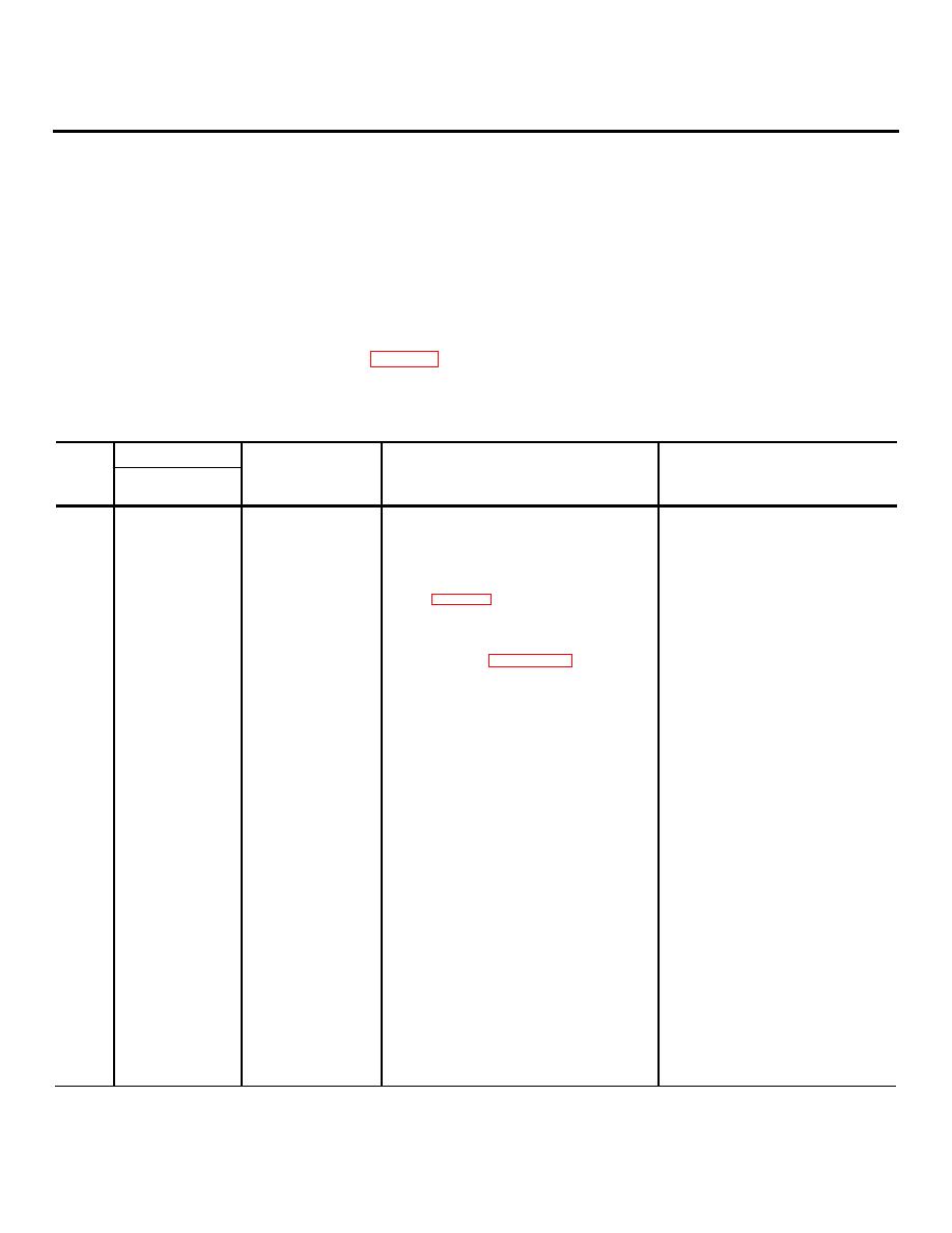
Table 3-1. Operator Crew Preventative Maintenance Checks and Services
B--Before
D--During
W--Weekly
Interval
Equipment will be
Item
Item to be
reported not ready
No.
B
D
W
inspected
Procedure
(Red) if:
1
Test set group.
Check to see that each switch, circuit breaker
Switch, circuit breaker, or control does
and control operates smoothly.
not operate smooth.
2
Control-interface unit.
Set all switches and controls in accordance
TEST NUMBER display reads other
than
with table 2-4. Set POWER ON/OFF
00.0.
switch to ON. Check TEST NUMBER dis-
play for 00.0 reading.
3
Test set group.
Perform control-interface unit BITE test in
One or more indicators do not light or
accordance with paragraph 2-5b(2).
TEST NUMBER display does not
indicate
00.5at completion of test
4
Digital tester.
Pace TEST switch indicator in up position
Any panel indicator does not light.
and observe all panel indicators fight.
5
Control-interface unit.
Check elapsed time meter operation.
Elapsed time meter not operating.
NOTE
Meter moves slowly; it only
changes at hourly intervals.
a. Place mode SELECT switch through the
a. MODE/POWER MODULE TEST ON
6
Control-interface unit.
following positions and observe the
indicator does not light in one or all
MODE/POWER MODULE TEST ON
positions.
indicator lights in each position:
NOTE
Disregard the momentary flashing
of MODE POWER SHORT indica-
tor.
(1) ENC MODULE TEST.
(2) DEC MODULE TEST.
(3) STE MODULE TEST.
b. Place MODE SELECT switch through
b. MODE/POWER UNIT TEST ON i or
the following positions and observe the
does not light in one or both positions
MODE/POWER UNIT TEST ON indica-
tor lights in each position:
(I) ENC UNIT TEST.
(2) DEC UNRT TEST.
7
Test set group.
Restore all switches to their OFF position
3-1
|
|
Privacy Statement - Press Release - Copyright Information. - Contact Us |
