 |
|||
|
|
|||
|
Page Title:
REPLACEMENT OF PRINTED CIRCUIT BOARDS |
|
||
| ||||||||||
|
|
 TM 11-6625-2884-30/NAVAIR 16-35TS3615-2
REPLACEMENT
(1) Position replacement -15 V dc Power Supply PS4 (7) and bracket (6)
on RF modulation assembly.
(2) Fasten PS4 to power supply bracket, using pan head screw and lock-
washers (4).
(3) Fasten hold down bracket (6) to RF modulation assembly, using pan
head screw and lockwasher (4).
(4) Solder 115 Vac input wires (2) and two output wires (3) to Power
Supply PS4, observing dc polarity.
(5) Reinstall caution plate (1), with five pan head screws, lock-
washers and flat washers.
(6) Replace RF modulation assembly in BTS as in paragraph 3-32b.
REPLACEMENT
OF
PRINTED
CIRCUIT
BOARDS
Replace either or both printed circuit boards in 1A3 or 1A4,
3-38.
CCA, Pulse Generator 1A3/1A4-A1
CCA, CS and Pulse Control 1A3/1A4-A2
as follows.
REMOVAL
a. Perform the following steps.
CAUTION
Disconnect all cables from rear of unit before
retracting it from case.
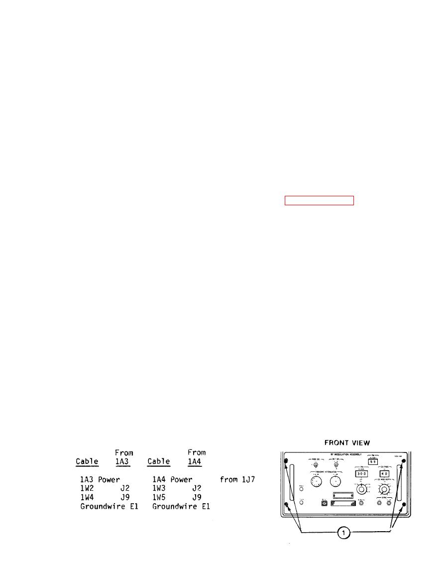
(1) Disconnect cables from rear of 1A3/1A4 as follows:
|
|
Privacy Statement - Press Release - Copyright Information. - Contact Us |
