 |
|||
|
|
|||
|
Page Title:
Table 2-1. Controls, Indicators and Connectors - Continued |
|
||
| ||||||||||
|
|
 TM 9-4931-378-13&P
Table 2-1. Controls, Indicators and Connectors - Continued
Control, Indicator
Function
or Connector
Index No.
Specific Function
Sw Pos
Selects fore-aft TAS signal
to be monitored.
Selects lateral TAS signal
to be monitored.
Selects vertical TAS signal
to be monitored.
Selects absolute pressure signal
to be monitored.
Selects air temperature signal
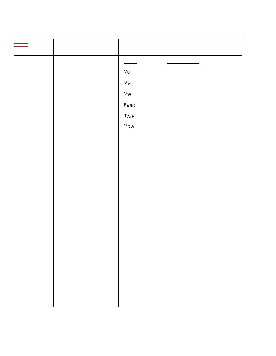
to be monitored.
Selects downwash velocity signal
to be monitored.
STAT 1
Selects status word 1 to be
monitored.
Selects status word 2 to be
STAT 2
monitored.
23
DATA WORD
Display 3-digit decimal word.
Decimal display DS12
Selects simulated radar altitude signal to be
24
RDR ALT FT Seven-position
transmitted to the EPU under test. Signals are
rotary switch S7.
selected in increments of 5 ft from 0 to 30.
AIR TEMP Co Ten position
Selects simulated centigrade air temperature
25
signal to be transmitted to the EPU under test.
rotary switch S6
Signals available are -54, -40, -30, -15,
0, 15, 30, 45, 60 and 71.
EPU 28V pushbutton switch
Opens the EPU 28 Vdc circuit so that current may be
26
S13
measured at AMPS test points TP13 and TP14.
Opens the LAI +15 Vdc circuit so that current may
LAI +15V pushbutton
27
switch S14
be measured at AMPS test points TP13 and TP14.
LAI 15V pushbutton
28
Opens LAI -15 Vdc circuit so that current may be
switch S15
measured at AMPS test points TP13 and TP14.
AMPS TP14 Gray
Negative test point to measure current of LRU input
29
power selected by S12.
AADS TEST 7-position
30
Selects signals to be monitored at TP15 and TP16 as
rotary switch S16
listed below.
2-4
|
|
Privacy Statement - Press Release - Copyright Information. - Contact Us |