Order this information in Print

Order this information on CD-ROM

Download in PDF Format


Click here to make tpub.com your Home Page

Page Title: d. Lead Resistance Error Adjust
Back | Up | Next

Click here for a printable version

Google


Web
www.tpub.com

Home


Information Categories
.... Administration
Advancement
Aerographer
Automotive
Aviation
Combat
Construction
Diving
Draftsman
Engineering
Electronics
Food and Cooking
Math
Medical
Music
Nuclear Fundamentals
Photography
Religion
USMC
   
Products
  Educational CD-ROM's
Printed Manuals
Downloadable Books


TM 55-6695-220-13&P c. 
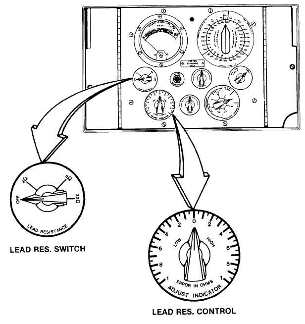
Lead Resistance Switch:  Setting of the LEAD RESISTANCE SWITCH by the operator inserts a precision resistor of either 2, 8 or 22 ohms into one leg of a null-galvanometer bridge circuit.  The resistance and thereby condition of the aircraft's thermocouple lead circuit may be determined by comparing it to this preselected resistance. d. Lead Resistance Error Adjust:  The operator varies the LEAD RESISTANCE ERROR ADJUST while observing the VOLTMETER pointer for a null condition.  The error in resistance indicated on the dial either high or low represents the difference in resistance between the preselected precision bridge resistor and that of the aircraft's thermocouple lead circuit. 1-5

Privacy Statement - Press Release - Copyright Information. - Contact Us - Support Integrated Publishing

Integrated Publishing, Inc. - A (SDVOSB) Service Disabled Veteran Owned Small Business