Order this information in Print

Order this information on CD-ROM

Download in PDF Format


Click here to make tpub.com your Home Page

Page Title: Figure 3-12. Printed Circuit Board Assembly
Back | Up | Next

Click here for a printable version

Google


Web
www.tpub.com

Home


Information Categories
.... Administration
Advancement
Aerographer
Automotive
Aviation
Combat
Construction
Diving
Draftsman
Engineering
Electronics
Food and Cooking
Math
Medical
Music
Nuclear Fundamentals
Photography
Religion
USMC
   
Products
  Educational CD-ROM's
Printed Manuals
Downloadable Books


TM 55-6695-220-13&P 3-17. CIRCUIT BOARDS - INSPECT/REPLACE.  (Contd) 3-17 (2)   Calibrate tester in accordance with para. 3-10.  When replacing either PC board. 
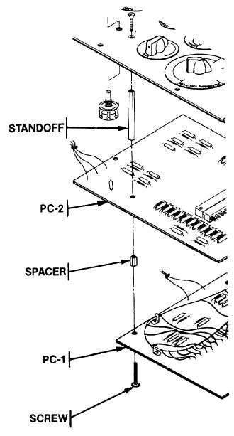
(3)   Secure PC boards to back of panel with four machine screws and three spacers (See Figure 3-12). (4)   Replace instrument panel in case, aligning eight screw holes. (5)   Use medium screwdriver to secure panel with eight screws. END OF TASK Figure 3-12.  Printed Circuit Board Assembly 3-31

Privacy Statement - Press Release - Copyright Information. - Contact Us - Support Integrated Publishing

Integrated Publishing, Inc. - A (SDVOSB) Service Disabled Veteran Owned Small Business