Order this information in Print

Order this information on CD-ROM

Download in PDF Format


Click here to make tpub.com your Home Page

Page Title: Figure 3-4. Case Hinge, Cover Stop, Cover Stop Screw And Spacer.
Back | Up | Next

Click here for a printable version

Google


Web
www.tpub.com

Home


Information Categories
.... Administration
Advancement
Aerographer
Automotive
Aviation
Combat
Construction
Diving
Draftsman
Engineering
Electronics
Food and Cooking
Math
Medical
Music
Nuclear Fundamentals
Photography
Religion
USMC
   
Products
  Educational CD-ROM's
Printed Manuals
Downloadable Books


TM 55-6695-220-13&P 3-11. CASE AND COVER --INSPECT/REPAIR/REPLACE.  (Contd) 3-11 b. 
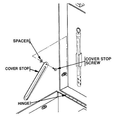
Repair and apply light oil to hinge and cover stops (See Figure 3-4). c. Straighten battery latches. 3.    REPLACE. a.    Removal. (1)   Remove damaged cover by removing hinge pin, cover stops, cover stop screws and spacers (See Figure 3- 4). (2)   Separate  damaged  case  from  the  other  parts  by  removing  the  cover  (Step  3-a.)  and  by  removing  the instrument panel (See para. 3-13.). b.    Installation. (1)   Attach new cover to case by installing hinge pin, cover stops, cover stop screws and spacers. (2)   Attach cover to new case (Step 3-c.) and reinstall instrument panel. END OF TASK Figure 3-4.  Case Hinge, Cover Stop, Cover Stop Screw And Spacer. 3-19

Privacy Statement - Press Release - Copyright Information. - Contact Us - Support Integrated Publishing

Integrated Publishing, Inc. - A (SDVOSB) Service Disabled Veteran Owned Small Business