Order this information in Print

Order this information on CD-ROM

Download in PDF Format


Click here to make tpub.com your Home Page

Page Title: Figure 2-1. Adapter Cables And Resistance Thermometer Test Cable
Back | Up | Next

Click here for a printable version

Google


Web
www.tpub.com

Home


Information Categories
.... Administration
Advancement
Aerographer
Automotive
Aviation
Combat
Construction
Diving
Draftsman
Engineering
Electronics
Food and Cooking
Math
Medical
Music
Nuclear Fundamentals
Photography
Religion
USMC
   
Products
  Educational CD-ROM's
Printed Manuals
Downloadable Books


TM 55-6695-220-13&P 
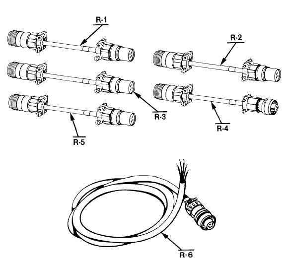
The five adapter cables stored in the right-hand-side compartment of the tester are shown in Figure 2-1. Figure 2-1.  Adapter Cables And Resistance Thermometer Test Cable To   avoid   having   the   VOLTMETER   pointer   strike   unnecessarily   the   full   scale   stop connect  the  tester's   RESISTANCE  THERMOMETER  TEST  LEAD   to   the   indicator's circular   connector   before   switching   the   RESISTANCE   AND   VOLTAGE   FUNCTION SWITCH  to  either  the  12  or  24  volt  position.    Similarly  return  the  switch  to  the  OFF position before disconnecting the test lead connector. 2-9

Privacy Statement - Press Release - Copyright Information. - Contact Us - Support Integrated Publishing

Integrated Publishing, Inc. - A (SDVOSB) Service Disabled Veteran Owned Small Business