|
| |
TM 55-6695-220-13&P
j.
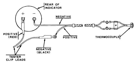
Indicator And Thermocouple Leads In Series Test Procedure. Disconnect the positive thermocouple lead from
the indicator and reestablish the airplane circuit by connecting the positive tester clip lead to the positive terminal on the
indicator and negative clip lead to the positive thermocouple lead. Since the thermocouple leads maintain the proper
circuit resistance, set the RESISTANCE AND VOLTAGE FUNCTION SWITCH to zero ohms. Follow the procedures in
paragraphs 2-1e. through i. as appropriate to complete the test.
NOTE
The indicator, thermocouple sensor, and leads must be at the same ambient
temperature in order that the potential thermal millivoltage output does not add
significantly to the tester output.
k.
Servo Thermocouple Indicator Test Procedures. Apply power to the indicator as delineated in the service
manual and allow it to stabilize at ambient temperature for 30 minutes under these powered-up conditions. If the
indicator is self-lighted, disconnect the lamp circuit during the tests. Use a short length of copper wire to establish a
circuit between the (+) jack of the TESTER STANDARD ONLY pin jacks and the (+) side or chromel wire connection as
delineated in the manual for the indicator. Likewise use a short length of alumel or constantan wire to form a circuit
between the (-) jack and the (-) side or alumel wire connection on the indicator. To retain the calibration of the tester
connect a 42 ohm resistor across the tester's clip leads.
2-6
|