|
| |
TM 55-6695-220-13&P
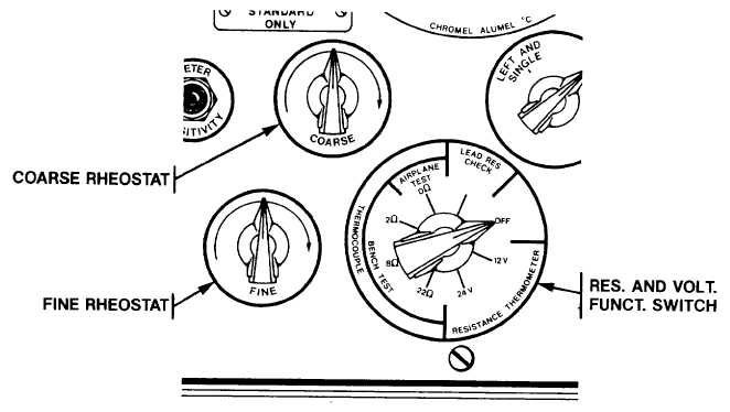
the correct condition is obtained. Rotate the RESISTANCE AND VOLTAGE FUNCTION SWITCH to either the 2, 8 or
22 ohm position to correspond with the thermocouple lead circuit resistance. This action insures that the tester's output
impedance equals that of the thermocouple and its lead circuit. Adjust first the COARSE RHEOSTAT and finally the
FINE RHEOSTAT to bring the VOLTMETER pointer up to the red line located at the full-scale position.
e.
Copper-Constantan and Iron-Constantan Indicator Test Procedures. Follow the preliminary procedures as
contained in paragraphs 2-1a. through d. and normalize the indicator at 20ºC by rotating the zero adjust with a small
screwdriver. Next step the TEMPERATURE SELECTOR SWITCH in each direction and note the difference between the
tester dial and indicator readings.
NOTE
The VOLTMETER pointer in its relation to the red line should be occasionally checked and
adjustments made to correct for varying battery conditions.
f.
The indicator service manual should be referred to for direction on the significance of these temperature errors.
When the final reading has been taken, turn the TEMPERATURE SELECTOR SWITCH to the
2-4
|