
TM 5-6350-275-24&P
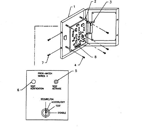
(5) Remove hardware, star washer, and nut from test activate switch (5) and remove switch from door assembly (1).
(6) Tag and disconnect wires from test verification lamp (6).
(7) Remove PWA assembly (2) from enclosure (1).
b. Installation
(1) Connect tagged wires to test verification lamp (6).
(2) Insert test activate switch (6) in door assembly (1) and secure it using star washer and nut.
(3) Align PWA (2) with standoff on front door assembly (1) and secure it using four phillips head screws (4).
(4) Connect tagged wires to TB1 (8) pins 1 through 14.
(5) Close front door assembly (1) and secure it with two round head screws (4).
(6) Connect 16 vac transformer to power source.
Figure 3-62. Removal and Replacement of Capacitance Proximity Sensor
3-211