
TM 5-6350-264-14&P-9
NAVELEX EE 181-AA-OMI-10A/E121 DZ-204
T.O. 31S9-2FSS9-1-9
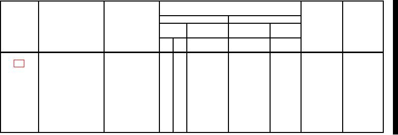
Section ll. MAINTENANCE ALLOCATION CHART
For
Audible Alarm (BZ-204)
(4)
(1)
(2)
(3)
(5)
(6)
MAINTENANCE LEVEL
TOOLS
FIELD
SUSTAINMENT
AND
GROUP
COMPONENT/
MAINTENANCE
EQPT REF
REMARKS
NUMBER
ASSEMBLY
FUNCTION
CODE
CODE
C
O
F
H
D
Audible Alarm
Inspect
0.4
1
Test
2.3
1
Repair
7.4
Replace
1.5
Eelectronics Assy
Test
0.4
1
Replace
0.9
NOTE
The "L" maintenance level is not included in column(4) of the MAC
Functions to this level of maintenance are identified by work time
figures in the "H" column, and an associated reference code is
used in the REMARKS column (6). This code is keyed to the
remarks and the SRA complete application is explained when required.
B-7
Change 4