
TM 5-6350-264-14&P-12
NAVELEX EE 181-AA-OMI-13A/E121 R1861-T1257
TO 31S9-2FSS9-1-12
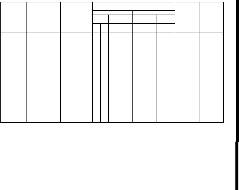
Section II. MAINTENANCE ALLOCATION CHART
For
Data Receiver (R-1861) and Data Transmitter (T-1257)
(1)
(2)
(4)
(3)
(5)
(6)
MAINTENANCE LEVEL
TOOLS
FIELD
SUST
AINMENT
AND
GROUP
COMPONENT/
MAINTENANCE
EQPT REF
REMARKS
NUMBER
ASSEMBLY
FUNCTION
CODE
CODE
C
O
F
H
D
01
Data Receiver
Test
1.5
Replace
0.3
Code Plug
Replace
0.5
*
02
Data Transmitter
Test
1.5
Replace
0.5
*
*Testing
of code plugs at direct support maintenance is limited to substitution with a
matched pair of plugs known to be serviceable.
NOTE
The `'L'' maintenance level is not included in column (4) of the MAC.
Function to this level of maintenance are identified by work time
figures in the `'H'' Colum, and an associated reference code is
used in the REMARKS column (6). This code is keyed to the
remarks and the SRA complete application is explained when
required.
B-7
Change 2