 |
|||
|
|
|||
|
Page Title:
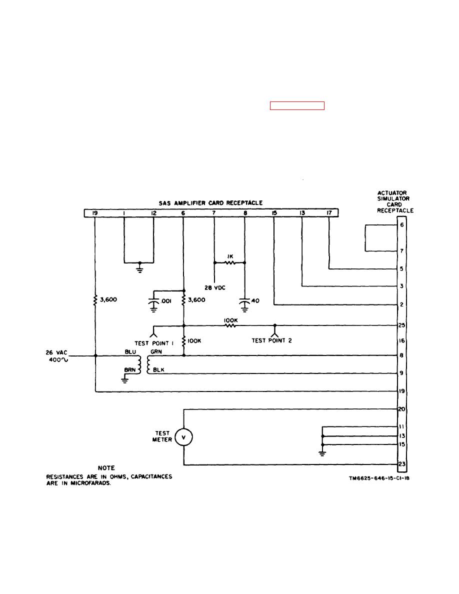
Figure 6-6. Actuator-simulator card, test setup. |
|
||
| ||||||||||
|
|
 C1, TM 11-6625-646-15
necessary. Prolonged heating can
(8) Using a heat sink, solder the leads to the
damage the card.
conductor.
(9) Coat the new part and the repaired area
(3) Heat the remaining solder in the mounting
with protective coating as directed in b above.
holes and remove it with a stiff bristle brush.
(4) Bend the replacement component leads
6-14. Connector Repairs
to fit the mounting holes.
Refer to paragraph 4-22.
(5) Insert leads in the mounting holes and
press the component firmly against the card.
6-15. Selection of Values for Actuator Simulator
Card Capacitor C607 and Resistor R648
(6) Cut the leads approximately 1/8 inch from
Capacitor C607 and resistor R648 in the filter and meter
the wiring side of the card.
rectifier circuits, respectively, are selected. When any
(7) Bend and press the leads against the
actuator simulator card
conductor.
Figure 6-6. Actuator-simulator card, test setup.
58
|
|
Privacy Statement - Press Release - Copyright Information. - Contact Us |
