 |
|||
|
|
|||
|
Page Title:
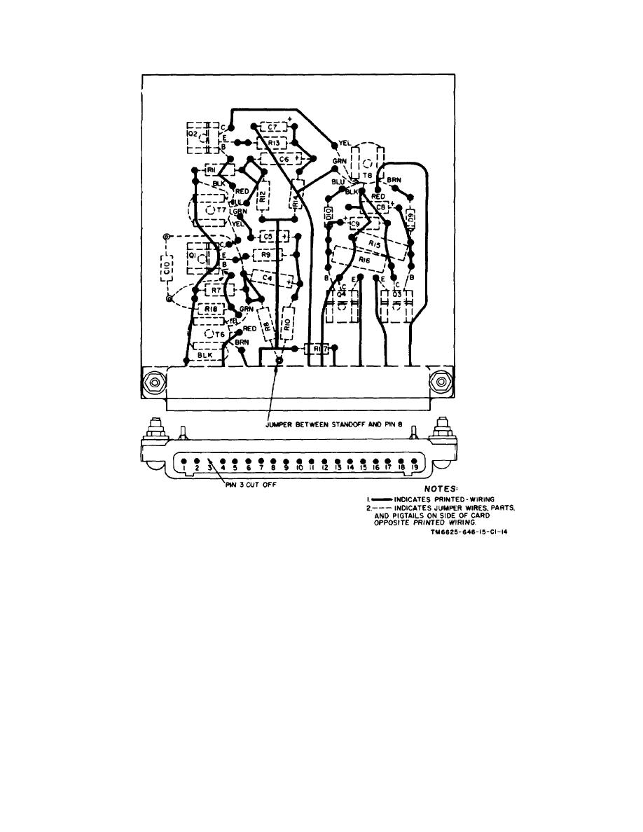
Figure 6-3. Amplifiers card, wiring diagram. |
|
||
| ||||||||||
|
|
 C1, TM 11-6625-646-15
Figure 6-3. Amplifiers card, wiring diagram.
the coating on the card do not allow bubbles to form.
(1) Remove the protective coating as
(d) Allow the card to dry in air for 5
directed in b above.
hours before installing it in the test set.
(2) Place a short length of flat bus wire over
the defect in the conductor and hold it firmly in place.
c. A printed-wiring conductor that has a hole, cut,
or notch that exceeds 30 percent of its width is defective
(3) Solder the entire length of the bus wire to
and must be repaired. Repair a defective conductor as
the conductor.
follows:
55
|
|
Privacy Statement - Press Release - Copyright Information. - Contact Us |
