 |
|||
|
|
|||
|
Page Title:
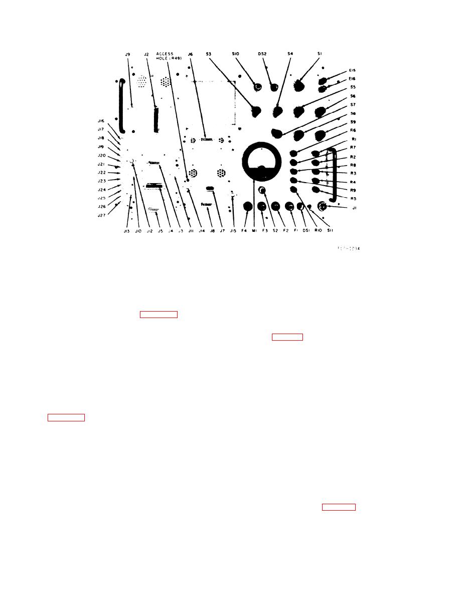
Figure 3-2. Test set, front panel component identification. |
|
||
| ||||||||||
|
|
 TM 11-6625-467-34
Figure 3-2. Test set, front panel component identification.
TOR switches where applicable. An X appearing in
3-7. Voltage and Resistance Measurements
the CIRCUIT SELECTOR switches column indi-
The normal voltage and resistance measurements
cates the position of the switch.
taken at the emitter, base, and collector of each
( 4 ) Special conditions for voltage measure-
t r a n s i s t o r are presented in table 3-2. Use these
ments are listed in the Other Conditions column.
measurements and the schematic diagrams to iso-
b. Resistance Measurements. The resistance
late troubles in the test set.
readings in table 3-2 were obtained under the condi-
WARNING
tions given in (1) through (4) below. Always make
Use insulated test probes when making re-
resistance measurements under these conditions or
quired voltage measurements. Always dis-
the readings obtained may be inaccurate.
connect the power cord from the test panel
(1) Make all resistance measurements with a
before touching any of the internal parts.
20,000 ohm-per-volt multimeter (AN/USM-223 or
Ground points of high potential to remove
equivalent).
residual voltage.
(2) Make all resistance measurements on the
a. Voltage measurements. The voltage readings
--
--
plug-in circuit cards with the circuit cards discon-
in table 3-2 were obtained under the conditions
nected from the chassis.
given in ( 1 ) through (4) below. Always make voltage
( 3 ) Make resistance measurements on the
measurements under these same conditions or the
chassis with all circuit cards in place and power dis-
readings obtained may be inaccurate.
connected.
( 1 ) Make all voltage measurements with a
( 4 ) Make all resistance measurements with
20,000 ohms-per-volt multimeter (AN/USM-223 or
respect to chassis ground or circuit card ground,
equivalent) unless otherwise specified.
w h i c h e v e r is applicable. make the resistance
( 2 ) Make all voltage measurements with
measurements with the negative ohmmeter probe
respect to chassis ground. Use the circuit board
connected to ground.
extender to extend the circuit card above the card
cage.
c. Table. The following table 3-2 lists the volt-
ages and resistance at the emitter, base, and collec-
(3) Make all voltage measurements with power
applied and the POWER SELECTOR switch set to
tor of each transistor in the test set. Unless other-
wise indicated, all voltage readings are positive de.
NORMAL. The CIRCUIT SELECTOR switch col-
The CIRCUIT SELECTOR switch settings and the
umn specifies the setting of the CIRCUIT SELEC-
3-6
|
|
Privacy Statement - Press Release - Copyright Information. - Contact Us |