 |
|||
|
|
|||
|
|
|||
| ||||||||||
|
|
 TM 11-6625-467-34
regulator output voltage appears entirely across
resistors A8R6 and A8R7. Resistor A8R6 is the out
put voltage control. Resistor A8R8 in parallel with
A8R6 reduces its effective resistance and allows a
more vernier control of the bias on A8Q3. When the
27.5 volt output becomes more negative, the volt-
age at the base of A8Q3 becomes more negative. As
the base voltage of A8Q3 goes negative, the collec-
tor current increases. The collector current path for
transistor A8Q3 is from the output of the filter cir-
cuit, through resistor A8R3, transistors A8Q1 and
A8Q3 and diodes A8CR10 and A8CR11 to ground.
The voltage drop across emitter resistor AlR3 in-
creases and causes the collector current of A8Ai to
decrease. The net effect is that the voltage at the
junction of the two transistors becomes more posi-
tive. The base of transistor A8Q2 becomes more
positive; its collector circuit internal resistance in-
creases and thus the voltage drops across it, which
causes the output voltage to decrease to the original
value.
b. Overcurrent Protector Circuit. The maximum
current that the -- 27.5 volt power supply delivers is
100 milliamperes. An overcurrent protector circuit
consisting of transistor A8Q4, resistor A8R4, and
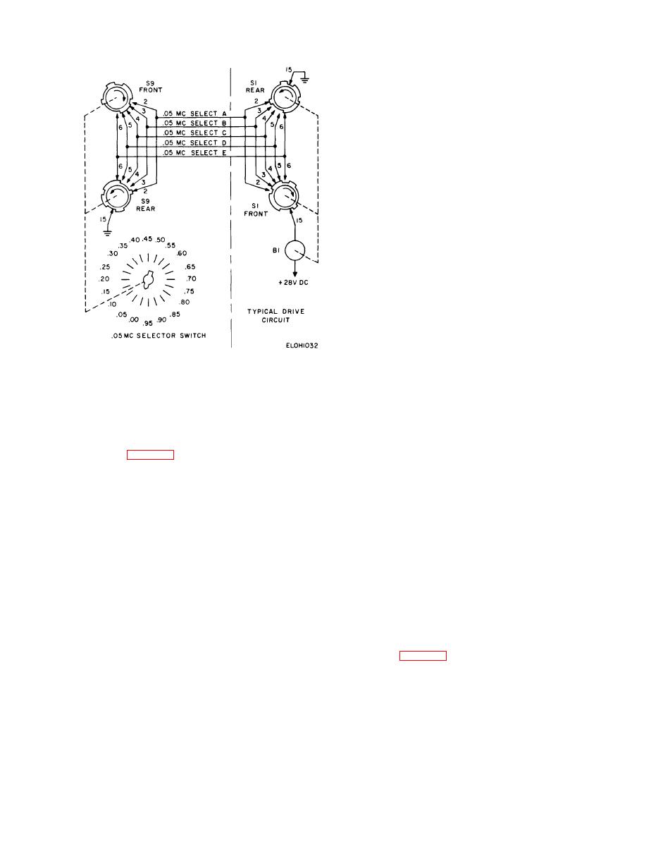
Figure 2-32. 0.05 MHz selector switch typical drive circuit,
associated components limits the total current to
simplified schematic diagram.
100 milliamperes. Assume that the output of the
regulator is shorted to ground. The voltage drop
ment of P1. Fuses F2 and F3 protect the primary cir-
cuit of transformer T1.
across A8R4 in the emitter-to-base circuit of A8Q4
increases and places a negative voltage on the base
2-38. --28 Volt Regulator
o f A8Q4. Transistor A8Q4 collector current in-
creases and places a positive voltage on the base of
transistor A8Q2. The positive voltage on the base of
The 27.5 volt power supply is a regulated power
A8Q2 causes its internal resistance to rise and thus
supply with a maximum output current of 100 milli-
the regulator output voltage to decrease; this condi-
amperes. T h e regulator circuit provides output
tion limits the output current to a safe value. Ca-
voltage regulation and control and over-current pro-
pacitor A8C5 is an antihunt feedback capacitor that
tection. The 27.5 volt regulated power supply is
prevents circuit oscillation. When the output cur-
discussed below.
rent changes, transistor A8Q4 senses the change as
a. Output Voltage Regulator. A bridge rectifier
described above. Capacitor A8C5 couples the chang-
circuit consisting of diodes A8CR1 through A8CR4
ing or step voltage to the base of A8Q3. The circuit
rectifies the ac output of transformer T1. A pi-type
of transistor A8Q3 amplifies and inverts the chang-
filter circuit, consisting of capacitors A8C1 through
ing voltage and applies it back to the base of A8Q2.
A8C4 and resistor A8R1, filters the output of the
T h i s action prevents oscillation by presenting a
bridge rectifier and applies the filtered dc voltage to
large negative feedback path for any ac voltage.
the collector of series-regulator transistor A8Q2.
Transistors A8Q1 and A8Q3 are connected in a
2-39. +28 Volt Regulator
cascade amplifier configuration. Zener diode A8CR9
maintains a constant bias on transistor Q1. Zener
The positive 27.5-volt regulator delivers + 27.5 volts
diodes A9CR10 and A8CR11 are the voltage refer-
dc at a current of 7.5 amperes to the test set circuits.
ence for the regulator and place a constant -- 10.2
The circuit is a series-regulator type and stabilizes
v o l t s on the emitter of transistor A8Q3. Zener
the output voltage over a wide current range. A
diodes A8CR12 and A8CR13 in series with resistors
bridge rectifier circuit consisting of diodes CR1
A8R6, and A8R7 form a voltage divider across the
through CR4 rectifies the ac output of transformer
regulator output. The two diodes have a constant
T1. Inductor L2 and the parallel combination of C2
16.4-volt drop across them regardless of the regu-
and C3 form an inverted L1-type filter that filters
lator output voltage; therefore, any change in the
2-79
|
|
Privacy Statement - Press Release - Copyright Information. - Contact Us |