 |
|||
|
|
|||
|
Page Title:
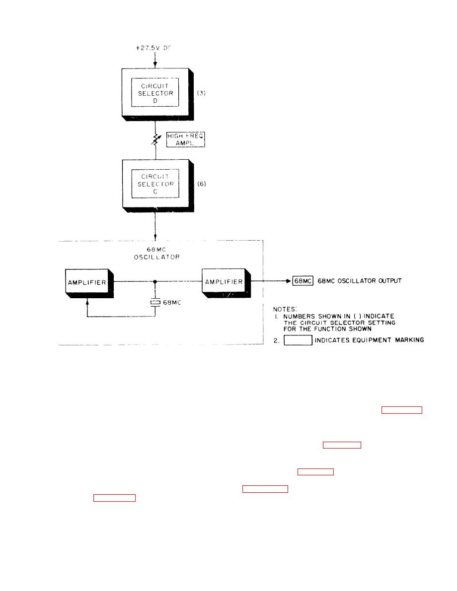
Figure 2-10. 68 MHz osillator circuit, functional diagram. |
|
||
| ||||||||||
|
|
 TM 11-6625-467-34
Figure 2-10. 68 MHz osillator circuit, functional diagram.
testing individual modules of Radio Set AN/
columns in the tables correspond to similarly titled
A R C - 5 4 . The switching arrangement consists of
columns in the operating procedures. Tables 2-1
four 10-position, 6-deck, front panel rotary switches
through 2-7 explain the function of each CIRCUIT
SELECTOR switch wafer. Only the switch wafers
labeled CIRCUIT SELECTOR A, B, C, and D. The
that perform a specific function for the test being
inputs and outputs of the AN/ARC-54 modules, as
well as the inputs and outputs of the functional cir
performed are listed. Table 2-1 includes the RF
JUMPER CABLE column. This column describes
cuits, connect to the switches. Setting the switches
the function of RF jumper cables connected as part
t o specified positions connects a complete test
of the test. Use tables 2-1 through 2-7 to determine
arrangement for a given module circuit. Operating
the testing configuration for any module circuit.
procedures given in TM 11-6625-467-12 list the
C I R C U I T SELECTOR switch setting for each
CIRCUIT SELECTOR switches, shows the routing
m o d u l e test. Tables 2-1 through 2-7 below are
of the test signals through the switches; refer to
keyed to the operating procedures in TM 11-6625
this figure to determine the signal flow for any CIR-
467-12. The STEP column. the TEST NAME
CUIT SELECTOR switch setting.
c o l u m n , and the CIRCUIT SELECT SWITCH
2-11
|
|
Privacy Statement - Press Release - Copyright Information. - Contact Us |