 |
|||
|
|
|||
|
|
|||
| ||||||||||
|
|
 TM 11-6625-467-12
power cable, six rf jumper cables (marked with
identification bands W1 thru W6), and a technical
manual is stored in the cover compartment. Spare
fuses, a spare pilot lamp, a tuning cover, and a
70-decibel (db) attenuator are stored on the inside of
the cover. Primary power for the test set is 115 volts
or 230 volts at a frequency from 50 to 100 Hertz
(Hz). The equipment contains a blower motor that
dissipates internal heat and provides forced air
cooling for the AN/ARC-54 chassis and power
supply modules under test.
b. A front panel connector is provided for each
AN/ARC-54 module to be tested The module tests
are performed by plugging an AN/ARC-54 module
into the specified connector on the test set, making
specified switch setings, and then noting the meter
reading. Function switches on the test set connect
the outputs of the various power supplies and
oscillators to the module under test. The function
switches also connect the module outputs to the
correct load and meter circuit. The meter provides a
relative indication of the performance of each
module circuit. Radio frequency voltages at 3
MegaHertz (MHz) and above are applied to the
modules under test through the rf jumper cables
from rf connectors on the test set.
c. The test set includes a self-check feature that
enables the operator to monitor the output of the
internal power supplies, oscillators, and other in-
ternal circuits on the front panel meter. This same
feature is used during the module tests to adjust the
oscillator output levels to specified values without
using an external meter.
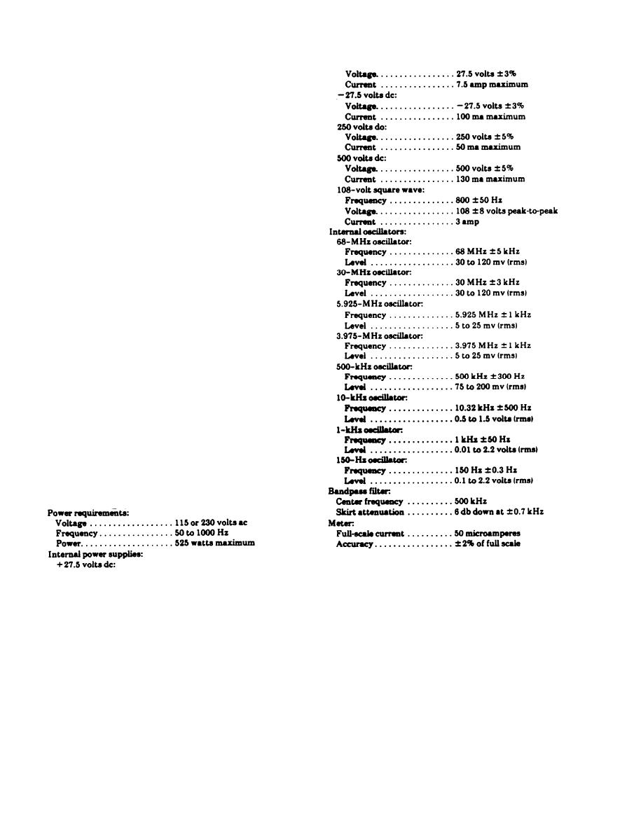
1-9. Tabulated Data
1-2
|
|
Privacy Statement - Press Release - Copyright Information. - Contact Us |