 |
|||
|
|
|||
|
Page Title:
Table 3-1. Test Set, Controls and Indicators |
|
||
| ||||||||||
|
|
 TM 11-6625-3023-14/ET904-AA/MMA-010/E154 TS3684/TO 33A1-12-1173-1
Table 3-1. Test Set, Controls and Indicators
Control/indicator
Function
POWER ON/OFF switch (S1)
Applies 115 VAC, 50, 60 or 400 Hz to
(SPST toggle)
test set in the ON position.
TEST switches (S2, S3)
When both TEST switches are
(momentary toggle switches)
depressed, the current path to the
zener diodes (D3 and D4) energizes
the selected output connector BULK
(J1), EXTERNAL (J2) or COAX (J3).
ESA select switch (S4)
Applies the test voltage to the
(rotary)
proper connector (BULK (J1),
EXTERNAL (J2), COAX (J3)) of the
particular ESA unit to be tested.
TEST switch (S5)
Places lamp L2 in parallel with ESA
SHORT or OPEN
device for the SHORT test and in
(DPDT toggle)
series with the ESA device for the
OPEN test.
Switch, TIP or RING (S6)
Enables selection of either the TIP
(DPDT toggle)
or RING wire of the transmission
line pairs (see note). In testing
BULK units it is only needed when
checking every wire of the unit
for a shorted condition since the
OPEN test on one associated wire
checks the entire unit.
TEST PASSED IF LIT (L2)
Illuminates to indicate a passed
indicator (green)
test.
AC power ON (L1)
Illuminates when 115 Volts, 50,
indicator (red)
60 or 4Q0 Hz is applied to test
set power supply circuit.
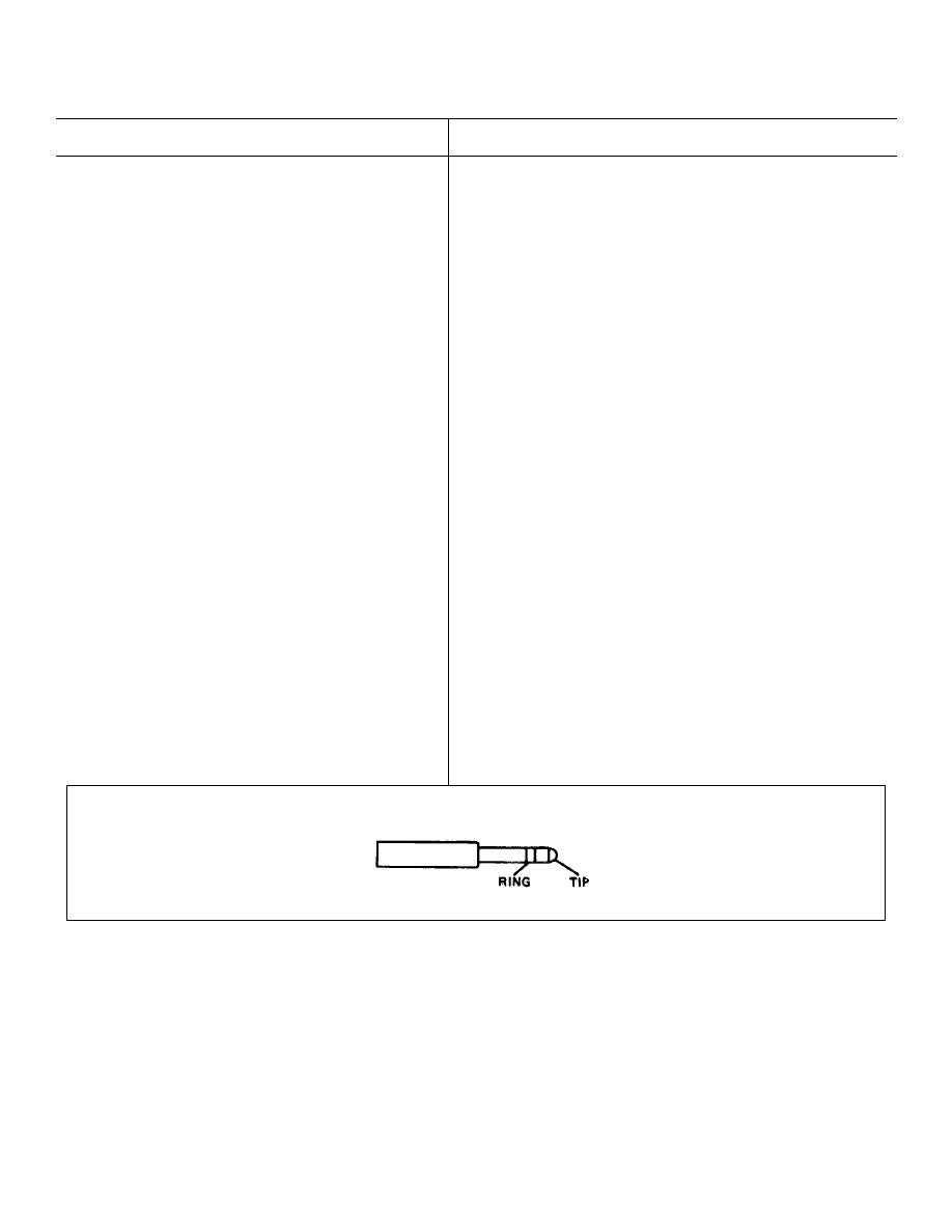
NOTE
Telephone Plug
3-3
|
|
Privacy Statement - Press Release - Copyright Information. - Contact Us |
