 |
|||
|
|
|||
|
Page Title:
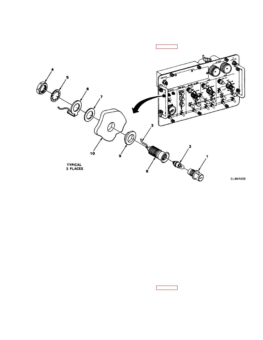
INDICATOR LIGHT DS1, DS2, AND DS3 REPLACEMENT. |
|
||
| ||||||||||
|
|
 TM 11-6625-2976-40
2-29. INDICATOR LIGHT DS1, DS2, AND DS3 REPLACEMENT.
MATERIALS/PARTS: Light, indicator (P/N 102SR1H23H1)
PRELIMINARY PROCEDURE Remove A6 and A8 assembly (para 2-19).
REMOVAL
1.
Remove indicator lens (1) and bulb (2).
2.
3.
Using wrench, remove nut (4), lockwasher (5), ground tab (6), and washer (7).
4.
Remove indicator (8) and rubber grommet (9) from front panel (10).
NOTE
Connected ground tab (6) will be reused.
INSTALLATION
1. Push indicator (8) and rubber grommet (9) into front paneL (10) and washer (7). Install
ground tab (6), lockwasher (5), and nut (4).
2. Using pliers, tighten nut (4).
4. Install bulb (2) and indicator lens (1).
FOLLOW-ON MAINTENANCE: Install A6 and A8 assembly (para 2-19).
2-75
|
|
Privacy Statement - Press Release - Copyright Information. - Contact Us |
