 |
|||
|
|
|||
|
|
|||
| ||||||||||
|
|
 TM 11-6625-2976-40
2-19.
A6 AND
REPLACEMENT.
(CONT)
A8 ASSEMBLY
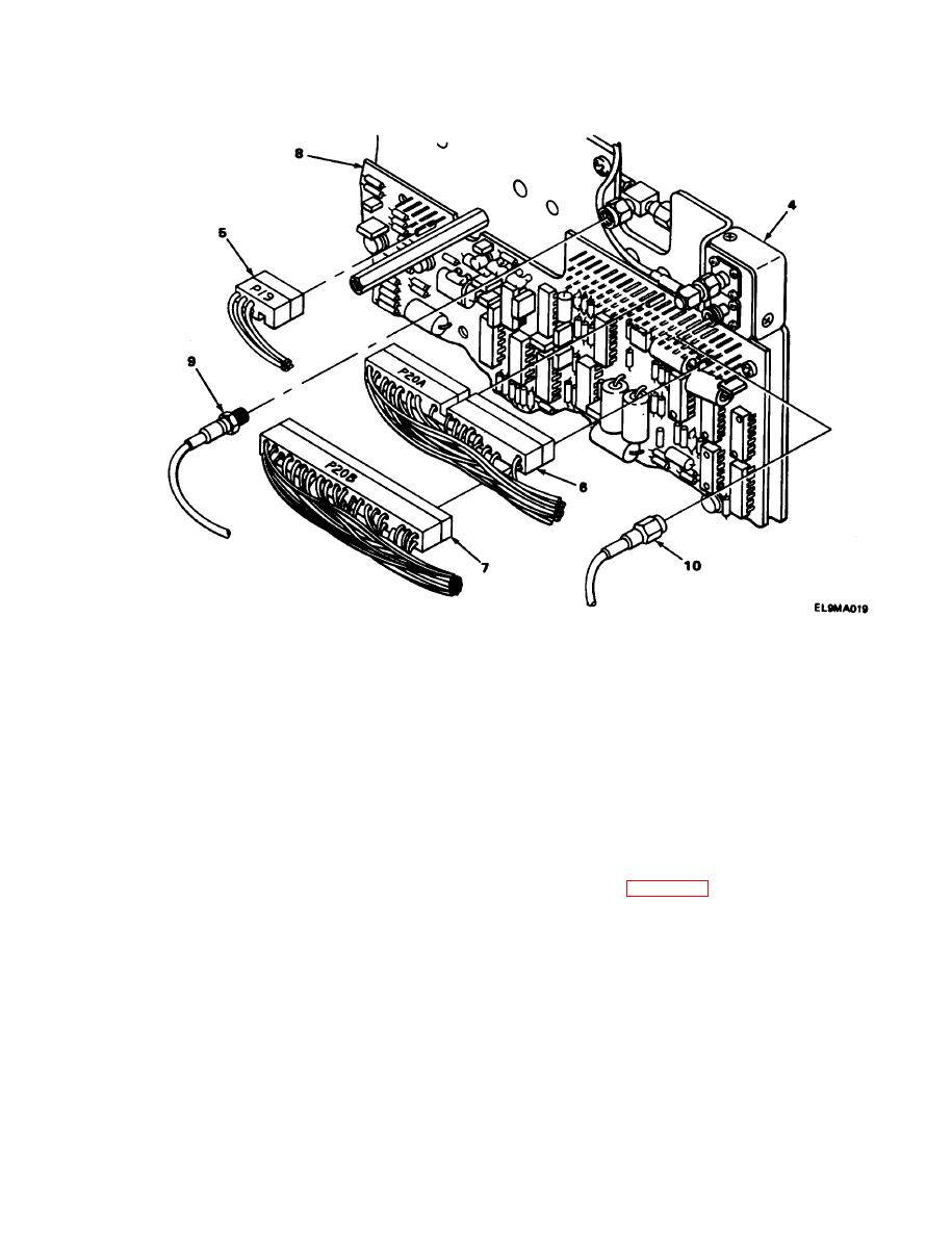
3. Unplug connectors P19(5), P20A (6), and P20B (7) from A6 circuit board (8).
4. Using wrench, remove rf cable connectors W8(9) and W10(10).
5. Remove A6 and A8 assembly (4) from front panel.
INSTALLATION
1.
Position A6 and A8 assembly (4) behind front panel (2).
2.
Install rf cable connectors W10 (10) and W8 (9) to A6 circuit board (8) and, using wrench,
tighten.
3.
Plug connectors P20B (7), P20A (6), and P19 (5) into A6 circuit board (8).
4.
Anne A6 and A8 assembly (4) with standoffs on front panel.
5.
Install three screws (3) and, using screwdriver, tighten.
Install three screws (1) and, using screwdriver, tighten.
6.
FOLLOW-ON MAINTENANCE: Install electronic components assembly(para 2-17).
2-63
|
|
Privacy Statement - Press Release - Copyright Information. - Contact Us |
