 |
|||
|
|
|||
|
Page Title:
MODULES A1 THROUGH A5 REPLACEMENT. |
|
||
| ||||||||||
|
|
 TM 11-6625-2976-40
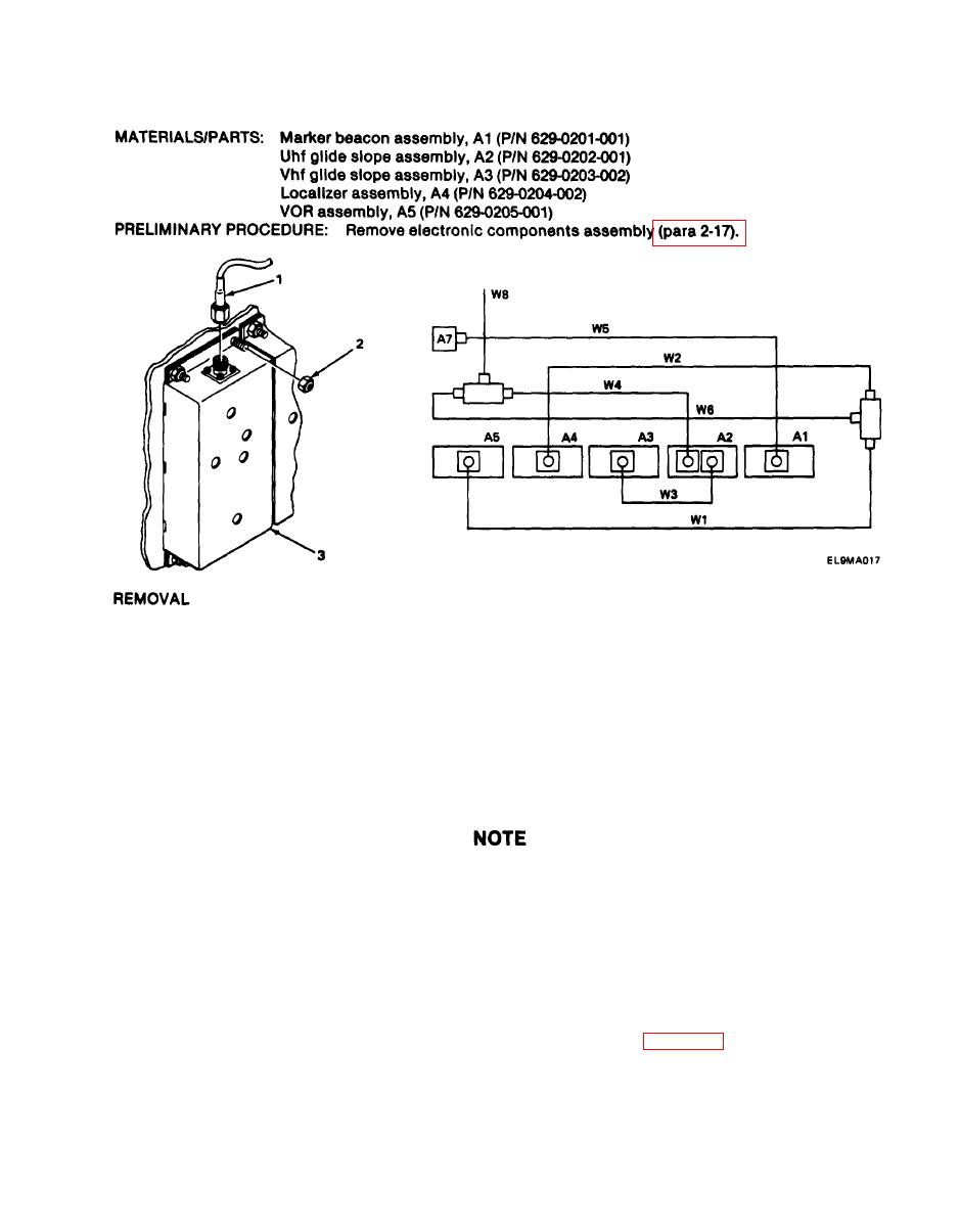
2-18. MODULES A1 THROUGH A5 REPLACEMENT.
NOTE
Steps given are typical for all modules. Module A2 has two rf cable connectors while all
other modules have only one rf cable connector.
1. Using wrench, remove rf cable connector (1).
2. Using socket driver, remove four nuts (2).
3. Carefully pull module (3) straight up from board to release from pins.
INSTALLATION
Steps given are typical for all modules. Module A2 has two rf cable connectors while all
other modules have only one rf cable connector.
See wiring diagram to aid in connector installation.
1. Carefully position module (3) on pins and push into place,
2. Install four nuts(2) and, using socket driver, tighten.
3. Install rf cable connector (1) and, using wrench, tighten.
FOLLOW-ON MAINTENANCE: install electronic components assembly (para 2-17).
2-61
|
|
Privacy Statement - Press Release - Copyright Information. - Contact Us |