 |
|||
|
|
|||
|
|
|||
| ||||||||||
|
|
 TM 11-6625-2976-40
1-15. BATTERY CHECK CAPABILITY. (CONT)
Sometimes more than one lamp will light when the battery is checked. This indicates that the + V and -V
batteries are at different voltage levels.
1-16. MODULATING CIRCUITS.
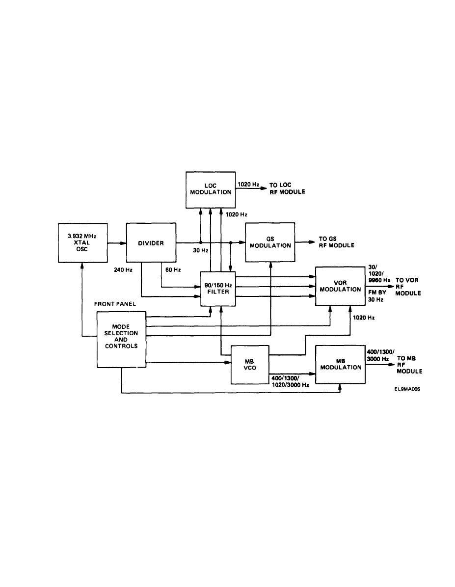
The circuit card assembly A6 modulating circuits generate modulating and control signals selected by
the front panel controls and apply them to LOC, GS, VOR, and MB rf modules. The fundamental fre-
quencies used to develop these signals come from two sources:
1. The 3.932 MHz crystal oscillator and frequency divider,
2. The MB vco.
The 3,932 MHz crystal oscillator and frequency divider, activated when S2 is placed in the ON posi-
tion, generate three fundamental frequencies: 30,60, and 240 Hz. The 30 Hz fundamental frequency
is applied to GS, LOC, and VOR modulating circuits. The GS and LOC modulating circuits use this
frequency to develop 90 and 150 Hz GS and LOC modulating frequencies, which are applied to GS and
LOC rf modules, in the VOR modulating circuit, 30 and 240 Hz fundamental frequencies work together
to produce signals corresponding to the front panel VOR bearing select switch setting, The VOR
modulating circuit uses the 60 Hz fundamental frequency as a reference signai to produce the 9960
Hz.
The MB vco provides the 1020 Hz modulating frequency for VOR and LOC modulating circuits and
develop the 400, 1300, and 3000 Hz signals needed for MB modulation.
1-9
|
|
Privacy Statement - Press Release - Copyright Information. - Contact Us |